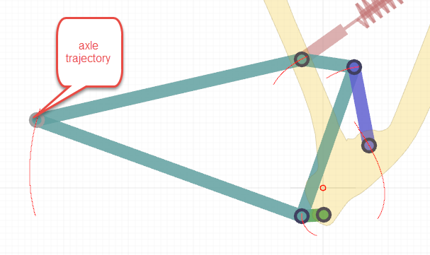
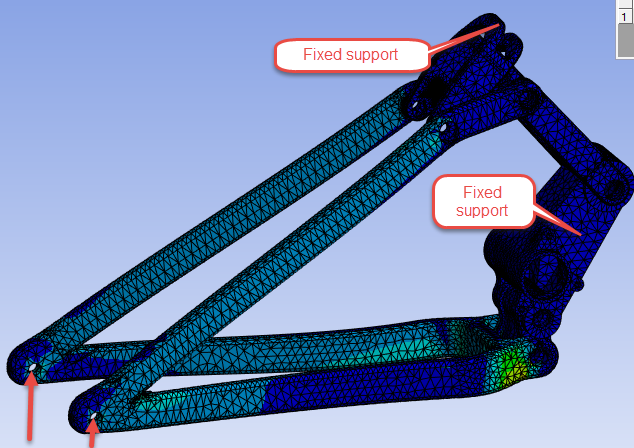
The Frame is ground for this mechanism, it doesn’t need to be in the model unless you need to see Frame stress.
There are three pivots on the frame. You can create a Revolute Joint to Ground at these three points. You are missing four bodies: two Pin bodies, a Cylinder body and a Piston body. Add these in then connect the Cylinder and Piston bodies with a cylindrical joint between them so the piston can slide along the cylinder. Use a revolute joint on the end of the cylinder to ground.
Three links come together (Cylinder, Fork, Top-link) that all need to rotate about a common Pin body. Slice the face of the Pin into five pieces along the length so you can put joints or contacts on the pin. You will need two outer faces to connect the Fork faces, two inner faces to connect the Top-link faces, and a center face to connect the Cylinder face.
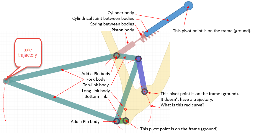
Three links come together (Long-link, Fork, Bottom-link) that all need to rotate about a common Pin body. Slice the face of the Pin into five pieces along the length so you can put joints or contacts on the pin.