-
-
April 18, 2024 at 1:17 pm
tirth.a2021
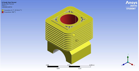
SubscriberI have a engine block model with rectangular fins. The purpose of the analysis is to conduct a steady state thermal analysis with a bore temperature of 100C, thermal conductivity of 170 W/mC and convection coefficient of 50 W/m^2C.
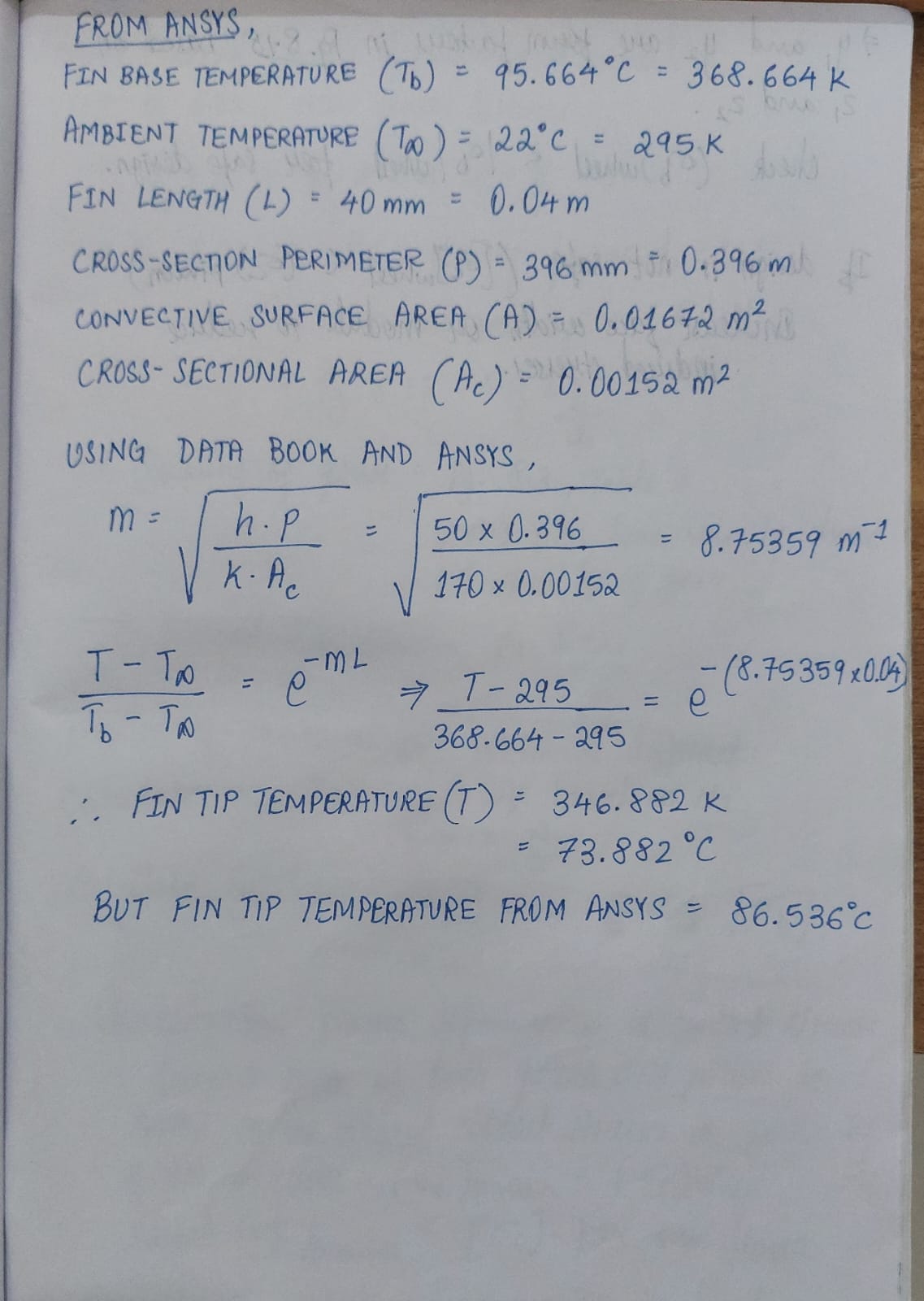
A named selection for convection includes all the outer surfaces, and the one for constant temperature includes the bore. So I have solved the model and obtained temperature, heat flux and some of these values at specific points using probes. My aim is to take the base temperature of a fin (temperature at the base of the fin), calculate the fin tip temperature from formulas in "Heat and Mass Transfer Data Book" and compare this with the obtained result from Ansys.
Why is there such a large deviation between hand calculated and ANSYS result? I know that ANSYS uses a different mathematical model than what is provided in a data book, but I believe this is a big error.
I also have trouble finding heat flow in Watts for the fins. The value of heat flux obtained from a probe at the fin surface, when multiplied with the surface area of the fin, is also very high compared to hand calculated result of heat flow for same fin.
Please help me to validate my results and/or suggest changes in my analysis so that I can close the gap between the results. Thanks.
-
April 23, 2024 at 7:35 am
Ashish Khemka
Forum ModeratorHi Tirth,
I think the forumula used by you is for a long fin and the forumula for a fin of finite length with heat convection is different. Can you please check the same? Also, if you can share the correlation from text book and simulation for using the formula then it might be helpful to comment.
Regards,
Ashish Khemka
-
April 27, 2024 at 6:59 am
tirth.a2021
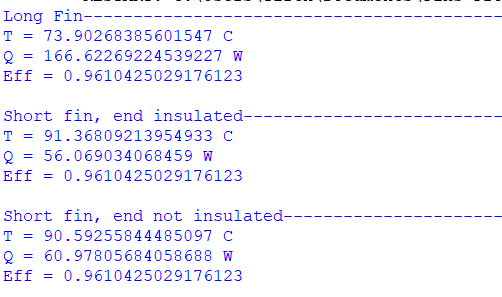
SubscriberThanks for the suggestion. Yes, you are correct, I had only used the formula for long fin. So what I did was, instead of declaring convection for both the surface of the engine block as well as the surface of the fin, I declared them seperately, and added a reaction probe result to get the heat flow from fins alone. Coupled with that I calculated fin tip temperature and heat flow for all 3 types of fins (long fin, short fin with insulated end, and short fin with end not insulated) as provided in the databook, with results as shown below:
Based on above values, I find that "short fin, end not insulated" has values closest to ANSYS results, so I'm going to go forward with that.
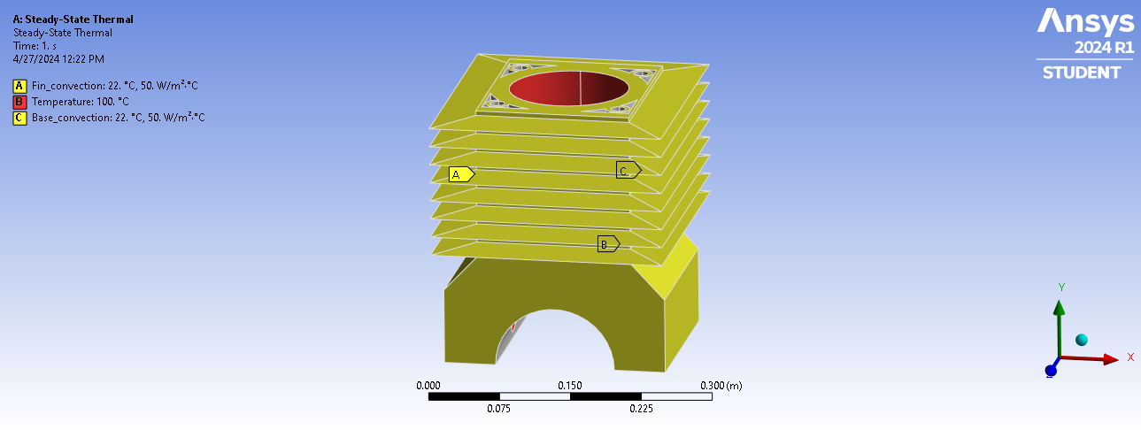
Just one other query: Here's a similar engine block but with triangular fins:
Here, I'm planning to use the same formulas for verification. But I need to know how to find the value of cross-sectional area and perimeter of the cross-section to input in the formula, since unlike rectangular fins, the cross-section changes along the fin here. Appreciate the help!
-
-
April 29, 2024 at 7:51 am
Ashish Khemka
Forum ModeratorHi,
I do not know the exact valu for this case but try using the same vaule as for a rectanguar fin and see if you notice a significant change.
Regards,
Ashish Khemka
-
- The topic ‘Help needed for steady state thermal analysis of rectangular fins and validation’ is closed to new replies.


-
4708
-
1565
-
1386
-
1242
-
1021

© 2026 Copyright ANSYS, Inc. All rights reserved.


