-
-
April 10, 2023 at 7:23 pm
Taiye Owu
Subscriber
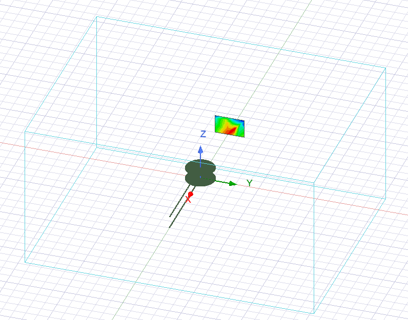
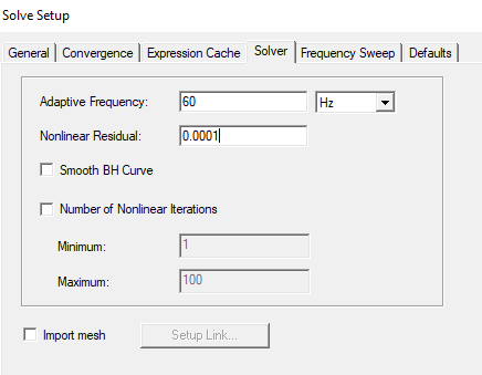
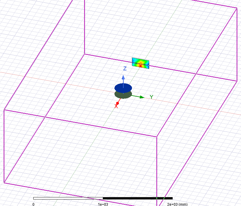
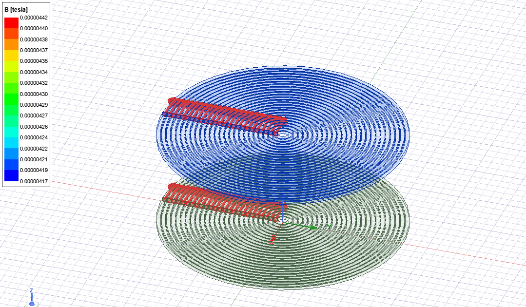
Please I need help on my simulation. I have a coil structure in my lab constructed for wireless power transfer, I am currently carrying out a simulation of that same coil structure using the same parameters, such as number of turns and dimensions. Now the problem is that the self and mutual inductance from my simulation results is far from my measured result in the actual system. The measured self inductance is 90uH, but my simulated result gives me 50uH. I initially was using magnetostatics solution type and thought that was the reason for the inaccuracy, but even when I changed my solution type to eddy current, it gives me only a bit higher result of 55uH. I also changed the initial mesh to be very fine, but still same results. Am I missing out on something or are there some other settings I need to do? I have attached relevant images for the top view, the isometric view and with region. My setup uses simulation error of 0.5% with 30 passes max and solves after convergence. I just need to know why my inductances are much smaller than the original system, cause I expect a bit of deviation, but not as much as I see. Thank you.
-
April 14, 2023 at 9:02 am
NKC
Ansys EmployeeHi Taiye,
It looks like the region size is less along the Z direction. can you increase the region size in all directions equally and see if the inductance result improves?
Regards,
Navya
-
April 14, 2023 at 3:48 pm
Taiye Owu
SubscriberAlright, I will do that and let you know thank you.
-
April 17, 2023 at 3:03 pm
-
April 17, 2023 at 3:28 pm
NKC
Ansys EmployeeHi Taiye,
If your result is changing with the change in region size means region size is still not enough.
I suggest you keep increasing region sizes in steps and observe the result. At some point, you will not see a change in results with an increase in region size, that is the minimum region size you need.
Regards,
Navya
-
April 17, 2023 at 4:00 pm
Taiye Owu
SubscriberOkay, I will do that and feed you back. Thank you
-
April 18, 2023 at 4:24 pm
Taiye Owu
SubscriberHello Navya, I have maxed out the region size and my inductance remains at 59uH. Is there something else I can do?
-
April 20, 2023 at 12:07 pm
NKC
Ansys EmployeeHi Taiye,
Another thing that needs to be changed is instead of giving the current as in and out from the boundary, please change it to a closed loop with a lesser length of lead wires, make a section and assign current excitation to that section.
Also, have you ensured both the test frequency and the frequency of excitation in the simulation are the same?
Regards,
Navya
-
April 20, 2023 at 3:36 pm
Taiye Owu
SubscriberHello Navya,
How do I set the frequency of excitation? I can't see anywhere to do that.
-
April 20, 2023 at 4:06 pm
-
April 20, 2023 at 4:12 pm
Taiye Owu
Subscriber-
April 24, 2023 at 3:08 pm
DELI
Ansys EmployeeHi Taiye, what is the value you got in the real test? Could you also try simulating 0.1Hz and comparing with DC test result?
-
-
April 24, 2023 at 3:18 pm
Taiye Owu
SubscriberThe real test is 90uH. Okay, I will try simulate with 0.1Hz and get back to you.
-
- The topic ‘Help In-accurate Simulation Results’ is closed to new replies.
- How does Ansys Twin Builder implement different simulation steps for subcircuits
- Simulation of capacitor combining eddy currents with displacement currents
- Compute near field simulation with current
- Double-sided LIM external circuit error
- HFSS: Using Q3D to solve the DC point
- Ansys Resonance simulatioin error
-
3140
-
1007
-
935
-
858
-
792
© 2025 Copyright ANSYS, Inc. All rights reserved.