-
-
April 19, 2022 at 8:43 am
nguyenminhhieu15122000
SubscriberHello all,
I am simulating the problem of rotational motion generating heat. I'm having some problems while solving the math problem
1. I'm not sure how to put the load at the center of the tire (currently, I'm using remote point - remote load)
2. I want the tire to move and rotate but I don't know how to set it up.
3. I want to rigid bodies the empty part of the tire that is mounted to the wheel frame but I don't know how to set it up
Please, somebody help me. Have a nice day.
April 20, 2022 at 3:11 ampeteroznewman
SubscriberCreate solid geometry of the tire and rim. Create surface geometry of the road. The road surface should interfere with the tire slightly.
Use a Transient Structural model. Make the rim and road surface rigid bodies. Mesh the tire with at least 2 quadratic elements through the thickness.
Use a revolute joint to ground on the rim. Use Bonded Contact to hold the tire to the rim. Use Frictional Contact between the tire and road surface.
Use a translational joint to ground on the road surface. Use a joint load, type =displacement to move the road surface. This will cause the tire and rim to rotate on the revolute joint.
April 20, 2022 at 2:07 pmnguyenminhhieu15122000
Subscriberthank you for your support.
I am simulating with tire model without rim. So I want rigid bodies instead of rim but I don't know how to set it up.
I'm using Couple Field Transient model as it can output temperature result.
I can make the tire move on the road surface, can make it rotate in place but cannot combine so that it can both turn and move forward.
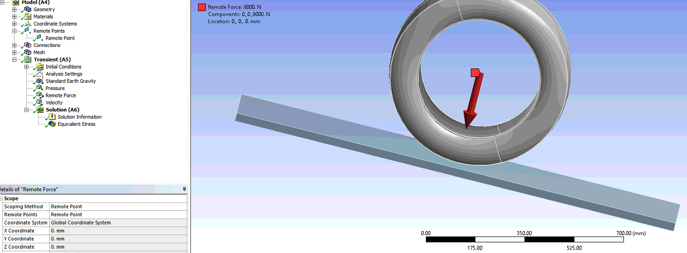
I am placing load at center using remote point to create point and then apply a force on that point. Is that correct?
April 20, 2022 at 10:57 pmpeteroznewman
SubscriberDelete the Remote Force. Delete the Velocity.
Use a revolute joint to ground on the tire bead surface and set the Behavior of the joint to Rigid. The joint will represent a rigid rim. The tire bead can only rotate.
Use a translational joint to ground on the road surface. Use a joint load, type =displacement to move the road surface.
The frictional contact between the tire tread and the road surface, combined with the geometric interference between the tire and the road along with the tire pressure will cause the tire tread to push against the road. When the road moves, the tire will rotate on the revolute joint.
The deformation of the tire tread caused by the pressure, the rolling and compression of the tire caused by the road will generate heat in the material. But the material model must have the correct thermal properties for the heat to be calculated.
April 21, 2022 at 4:33 amnguyenminhhieu15122000
Subscriberthank you for your support.
I think to give the speed of the tire equal to the speed of the car, with the load acting on it and the pressure.
So the tire subsidence is due to the pressure and its material?
I'm also making a drum model.
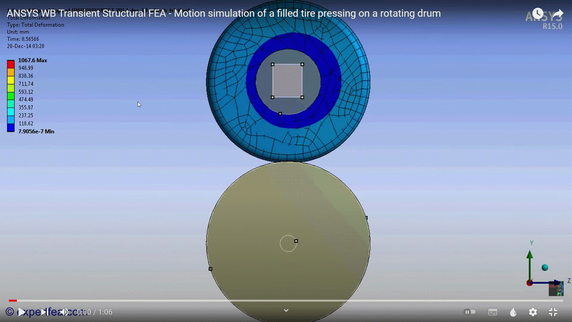
I have done the revolute, frictional settings in the connection. I'm wanting to have the subsidence as shown below but I haven't set it up yet. (https://www.youtube.com/watch?v=sV69UfWp1gQ)
April 21, 2022 at 6:24 ampeteroznewman
SubscriberA drum is simpler than a flat road because you don't run out of road!
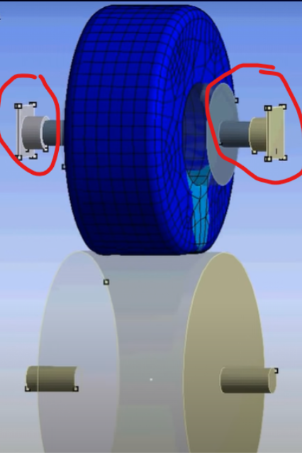
What I see in that video is an extra rigid body in the model, let's call it the axle. Instead of a revolute joint to ground scoped to the tire bead, use a revolute joint to the axle scoped to the tire bead. Put a translational joint to ground scoped to the axle. Now the tire can be tangent to the drum at time=0. The first step in the simulation can be to ramp the tire pressure up from 0 to the 32 psi or whatever pressure you want. That will cause the tire to make a small contact patch.
The second step in the simulation can be to move the axle closer to the drum. This will cause the contact patch to get slightly larger and represents 1/4 of the weight of the car being supported by one tire. You can plot the reaction force on the translation joint to see how much force the tire is supporting as the displacement of the axle toward the drum develops. You can rerun the simulation with more or less translation of the axle in order to get the desired reaction force.
The third step in the simulation can be to rotate the drum. Ramp the angular velocity from 0 up to the desired wheel speed. Step four can be a constant wheel angular velocity to allow heat to build up.
April 21, 2022 at 9:32 amnguyenminhhieu15122000
Subscriberthank you for your support.
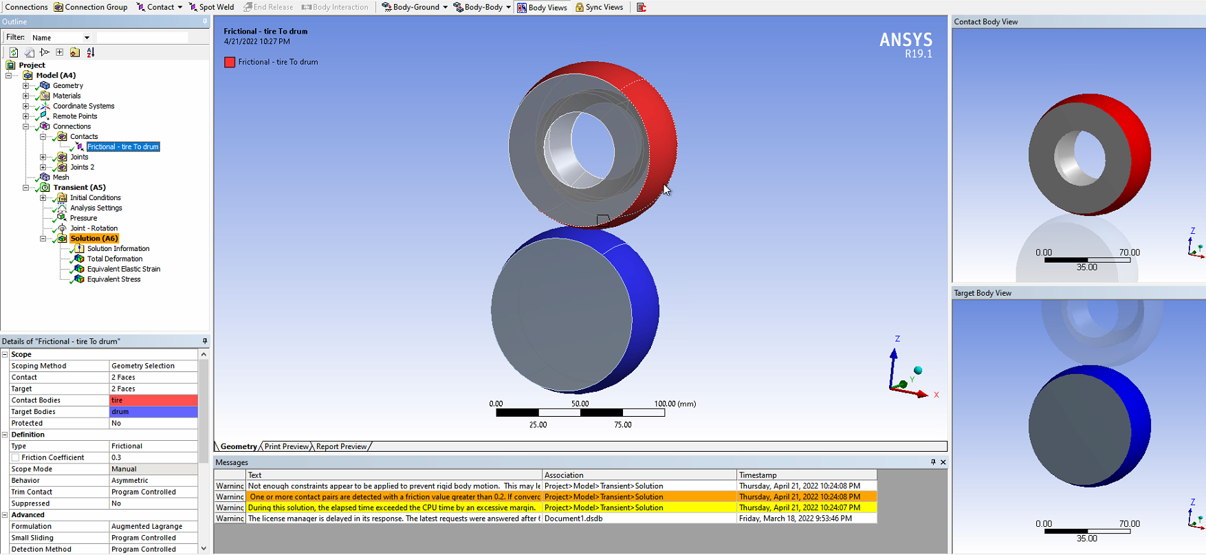
The video above is for my reference (maybe they do the same with experimental models). Here, I would like to have a subsidence like in the video. I simulated with simpler model as shown below.
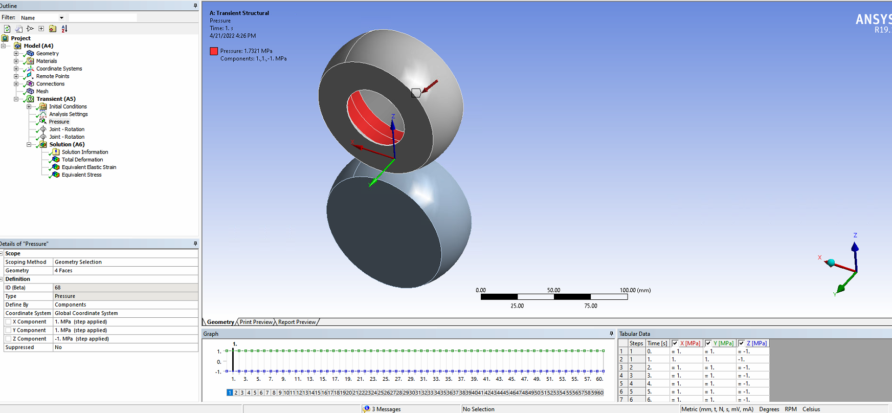 Currently, I just use the tire pressure set as shown below. What settings do I need to add to get what I want in the video? Thank you again.
April 21, 2022 at 9:41 ampeteroznewman
SubscriberDelete the Joint Rotation load on the Tire. Keep the Joint Rotation load on the Drum.
I thought the Drum would be a cylindrical surface, not a crowned surface.
April 21, 2022 at 11:55 amnguyenminhhieu15122000
SubscriberYes I know it. I will revise the model later.
But, If Delete the Joint Rotation load on the Tire, how will the tire rotate?
April 21, 2022 at 12:20 pmnguyenminhhieu15122000
SubscriberIf lucky, can you help me to set up this model? Thank you very much.
April 21, 2022 at 12:24 pmpeteroznewman
SubscriberThe frictional contact between the tire and the drum will rotate the tire.
I don't have access to ANSYS as I am travelling right now, so you will have to show screen snapshots if you want help.
April 21, 2022 at 3:32 pmApril 21, 2022 at 11:04 pmpeteroznewman
SubscriberShow the details of each joint.
Insert a Contact Tool under the Connections folder and Evaluate Initial Contact Status and show the table.
Do you have an axle body and a translation joint as I described above?
April 22, 2022 at 4:32 amnguyenminhhieu15122000
Subscriberthank you for your support.
The details of each joint.
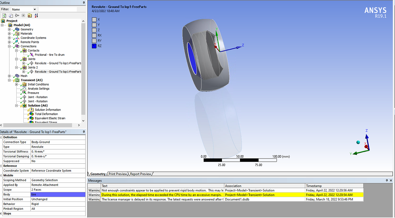
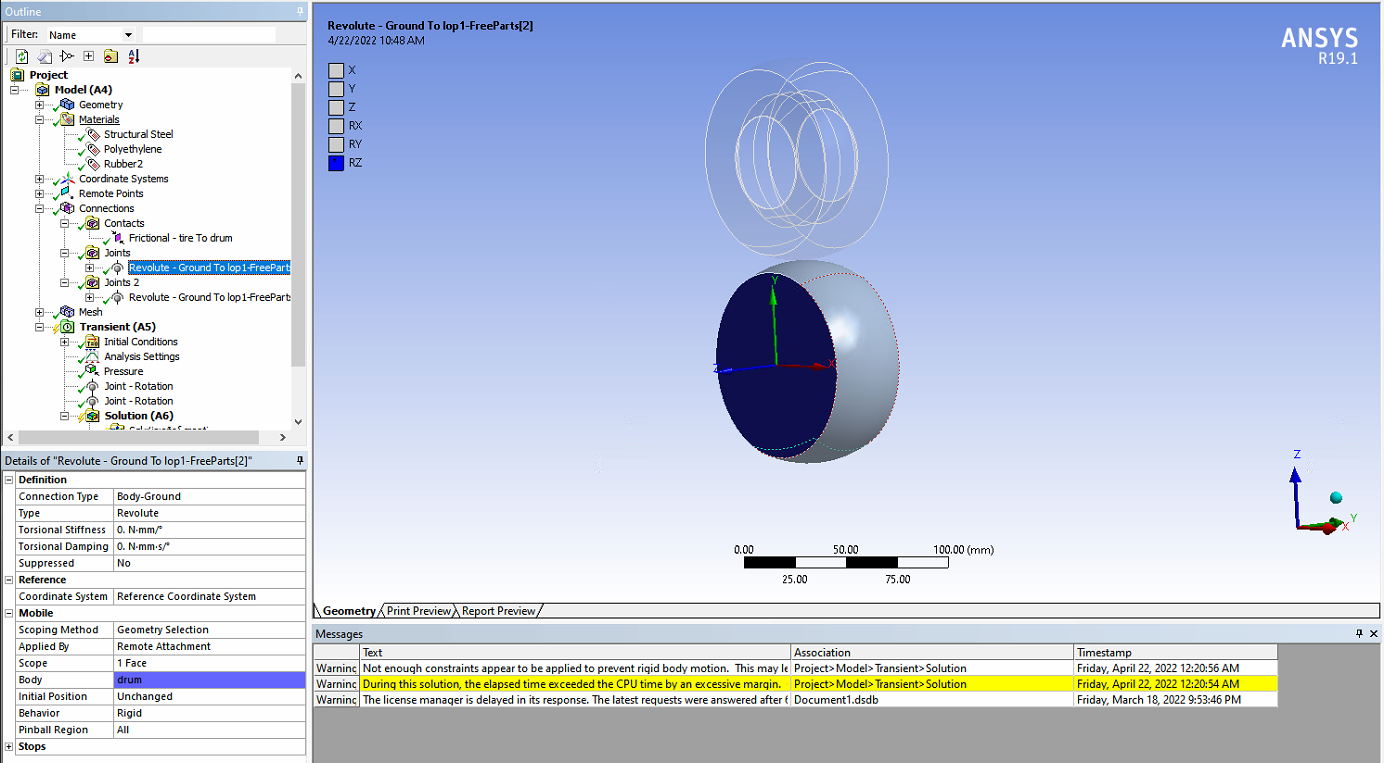 My understanding is that you want to have a axle like the picture and let it move down the drum.
Use a revolute joint to the axle scoped to the tire bead.
Put a translational joint to ground scoped to the axle, Use a joint load, type =displacement and move the axle closer to the drum.
April 22, 2022 at 10:03 ampeteroznewman
SubscriberYou show a Revolute Joint to Ground scoped to the tire bead.
You need a Revolute Joint to the Axle scoped to the tire bead.
April 22, 2022 at 12:35 pmnguyenminhhieu15122000
SubscriberBecause my English is not good, so I want to ask again for more clarification or you can draw the picture below so I can understand it better
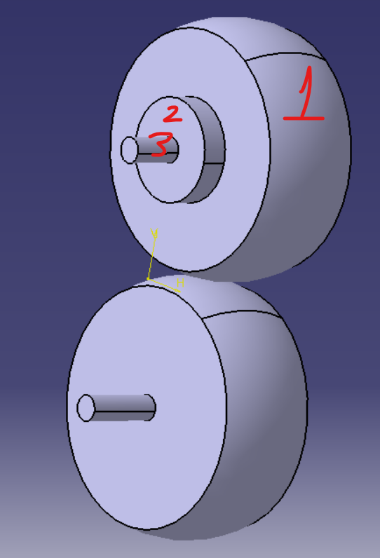
I create the Axle compared to the old model. (The tire model I drew is simpler than the real one)
You made suggestions like:
Instead of a revolute joint to ground scoped to the tire bead
Use a revolute joint to the axle scoped to the tire bead.
Put a translational joint to ground scoped to the axle
I consider tire bead number 1, axle number 3, ground scoped what is the number, sir? (I don't understand this place)
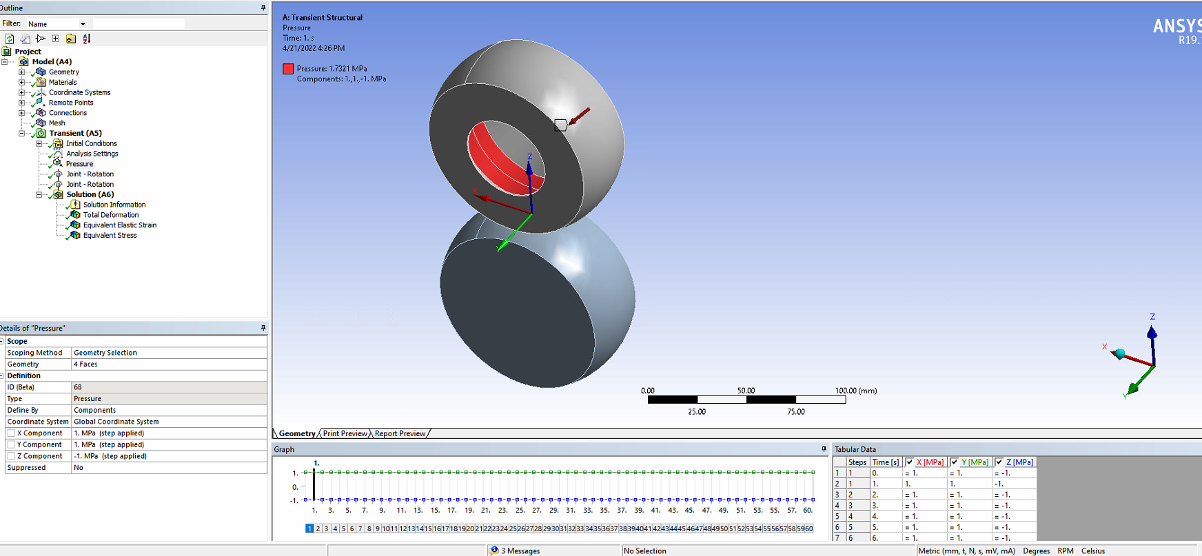
 Is the pressure setting like the 2nd picture below ok?
Thank you for your support.
April 23, 2022 at 12:08 ampeteroznewman
SubscriberThe pressure is wrong. Do not Define By Components. Let the pressure be applied normal to the face.
The revolute joint goes between the Tire (1) and the Axle (3).
The translation joint goes between the Axle (3) and Ground and the direction allows the movement of the tire toward the drum. You can edit the Coordinate System under the Joint to point the free axis in the correct direction.
April 23, 2022 at 3:44 amnguyenminhhieu15122000
SubscriberCan you help me check?
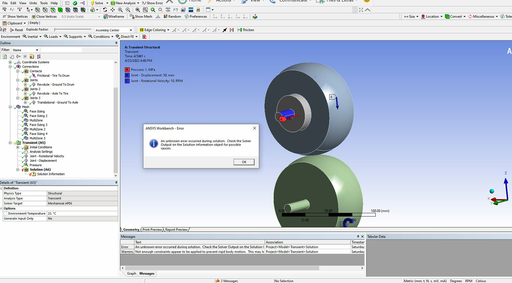
Firstly, contact between the Tire(1) and the Axle (3)
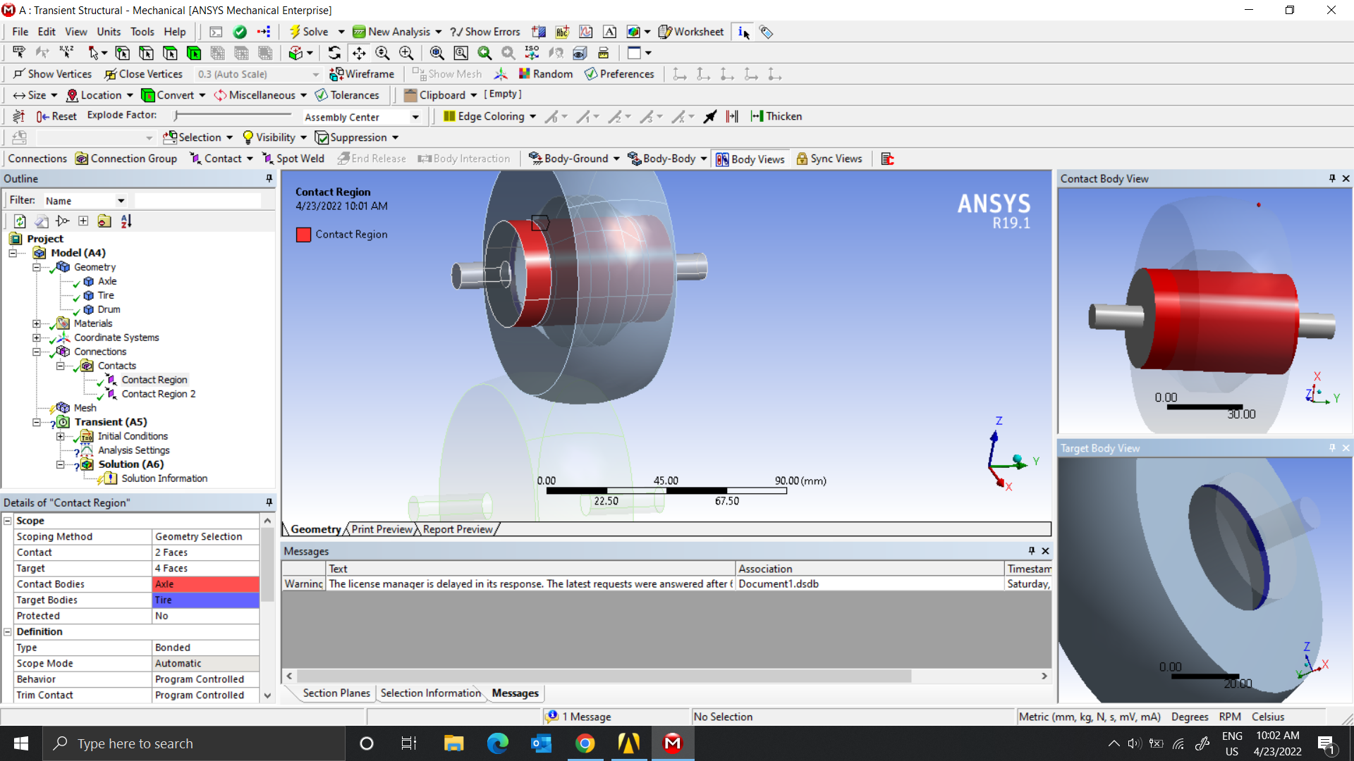 Secondly, the Frictional between the tire and drum
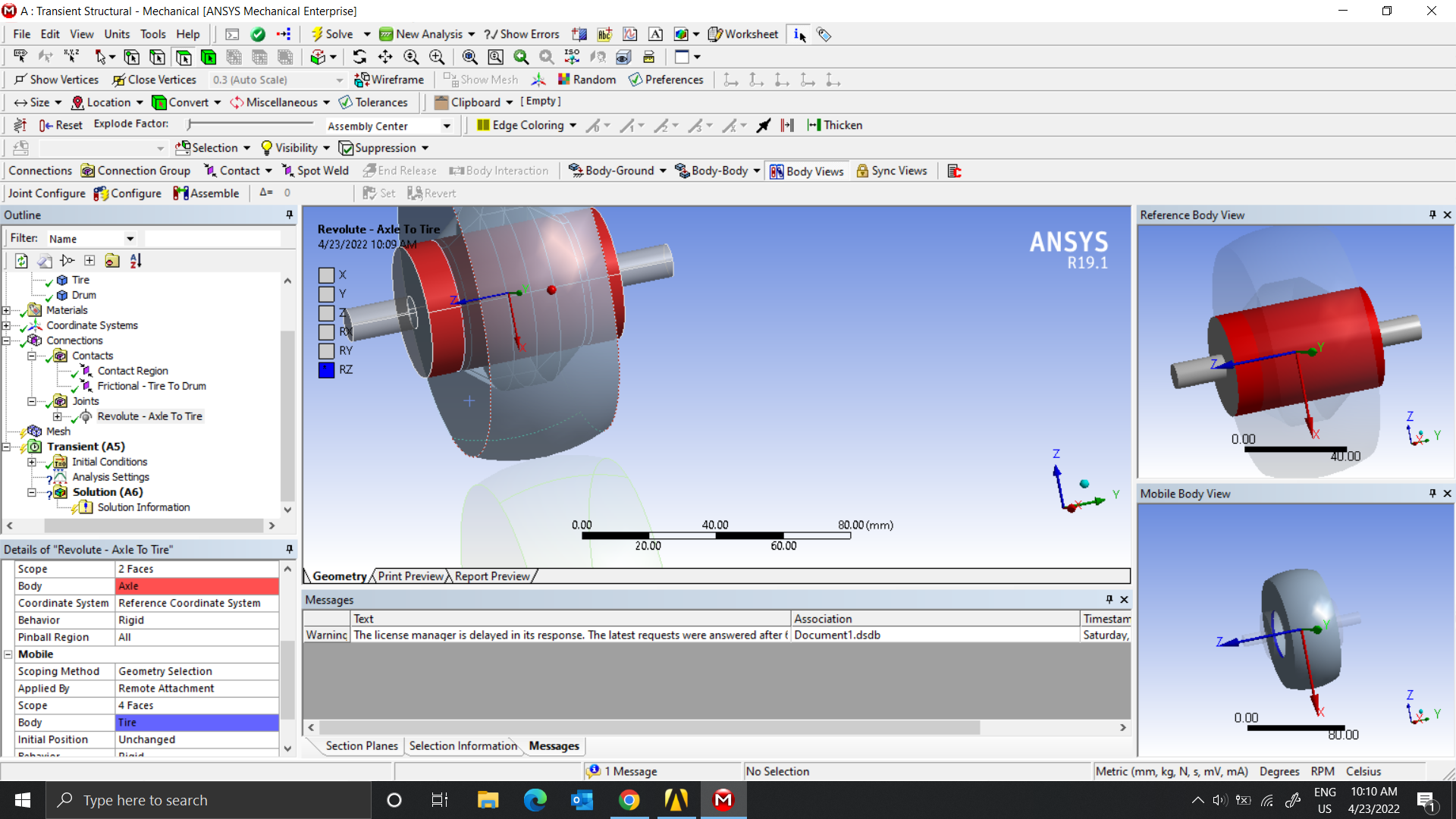
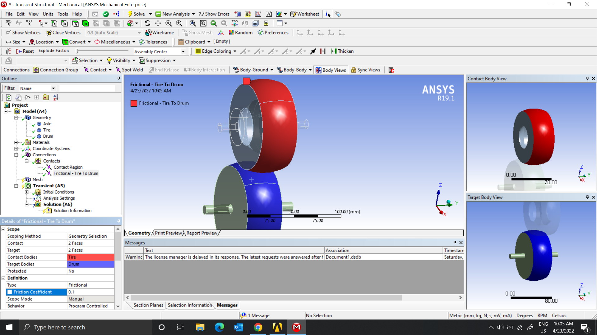 Next, revolute between the Tire and the Axle
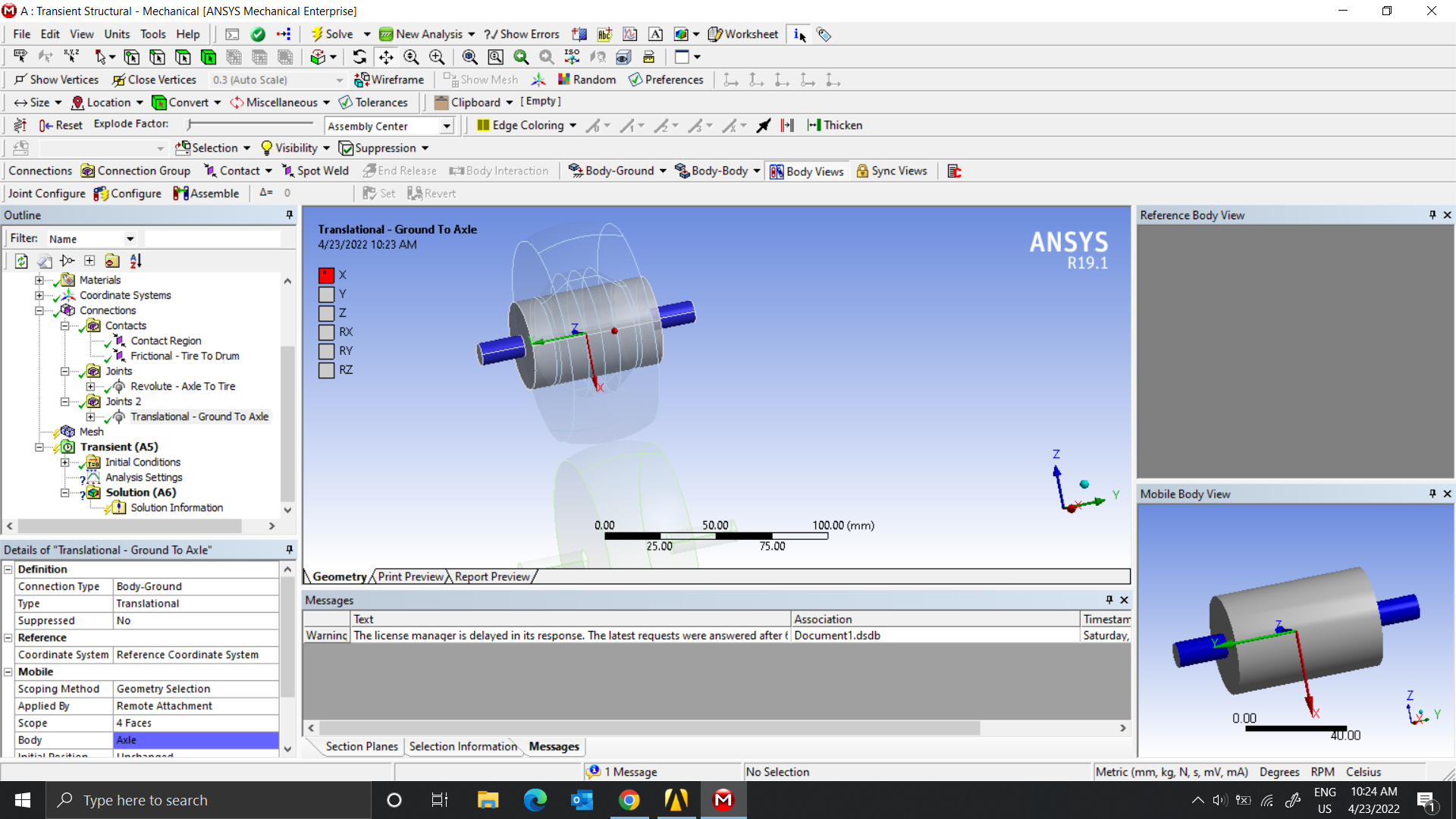
 Next, The translation joint goes between the Axle (3) and Ground
 Next, the Revolute Joint to Axle to Tire
 Next, a translational joint to ground to the axle
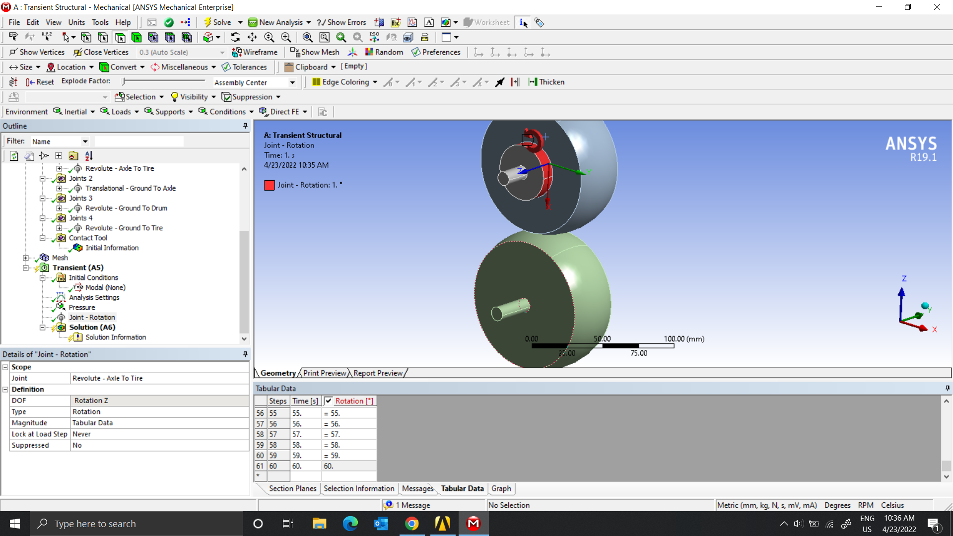
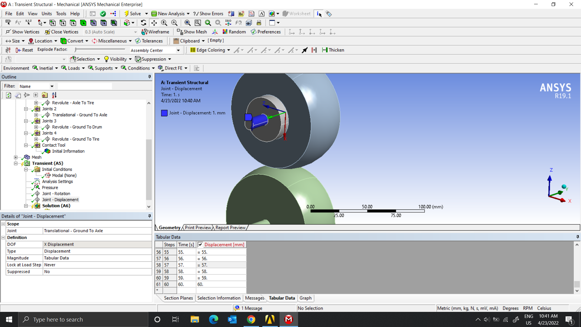 Next, Revolute joint to ground to the Tire
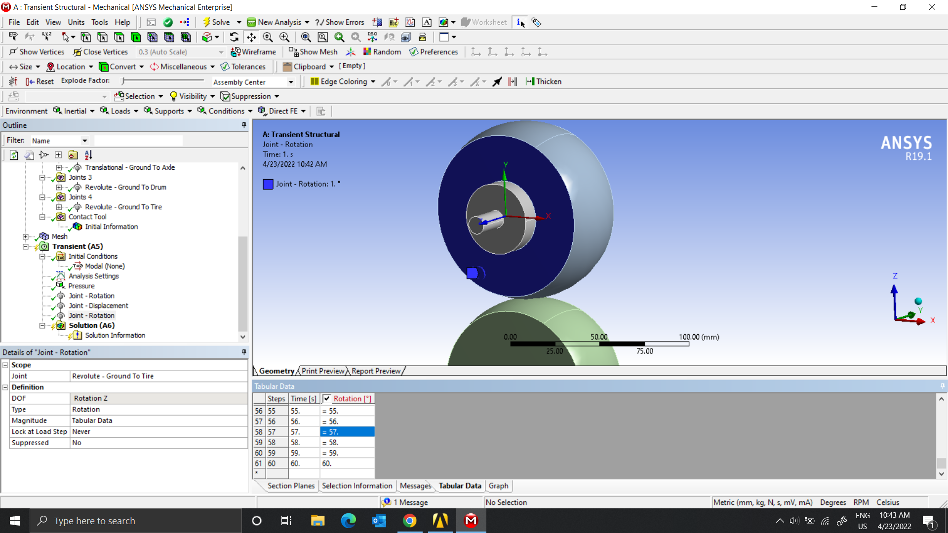 Next, Revolute joint to ground to the Tire
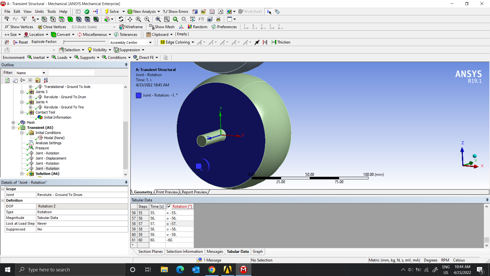 Thank you for your support.
April 23, 2022 at 5:27 ampeteroznewman
SubscriberDelete the Contact Region between the Axle and Tire. The Revolute joint connects the Axle and Tire. The Contact Region prevents the tire from rotating on the axle.
What is Joint 4 for? You do not want a joint between the Tire and Ground. Delete it.
You only want one Revolute Joint Load, delete the extras. Keep the load on the Revolute Drum to Ground. Make the load an angular velocity instead of a displacement.
You don't need 60 steps to turn the tire. You can do the analysis in 4 steps.
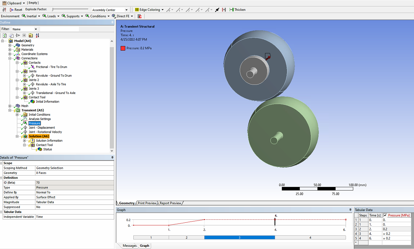
Step 1, end time 1 second, ramp the Pressure up from 0 to some psi.
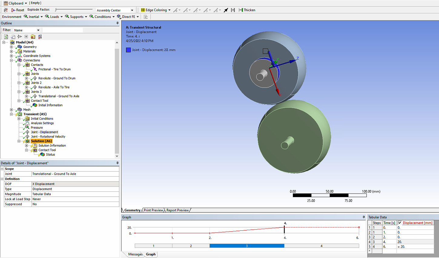
Step 2, end time 2 seconds, ramp the Joint Displacement up to some number of mm to squash the tire on the drum. Keep the pressure constant.
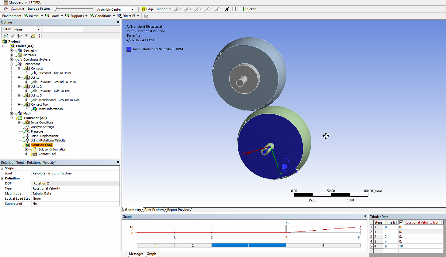
Step 3, end time 4 seconds, ramp the Drum Revolute Joint Velocity up to some specific angular velocity, keep the pressure constant and keep the displacement constant.
Step 4, end time 6 or 60 seconds, keep the Revolute Joint Velocity at a constant angular velocity equal to the value at the end of step 3. Keep the pressure and displacement constant. Step 4 is when the heat will build up in the tire.
April 23, 2022 at 9:54 amApril 24, 2022 at 5:15 ampeteroznewman
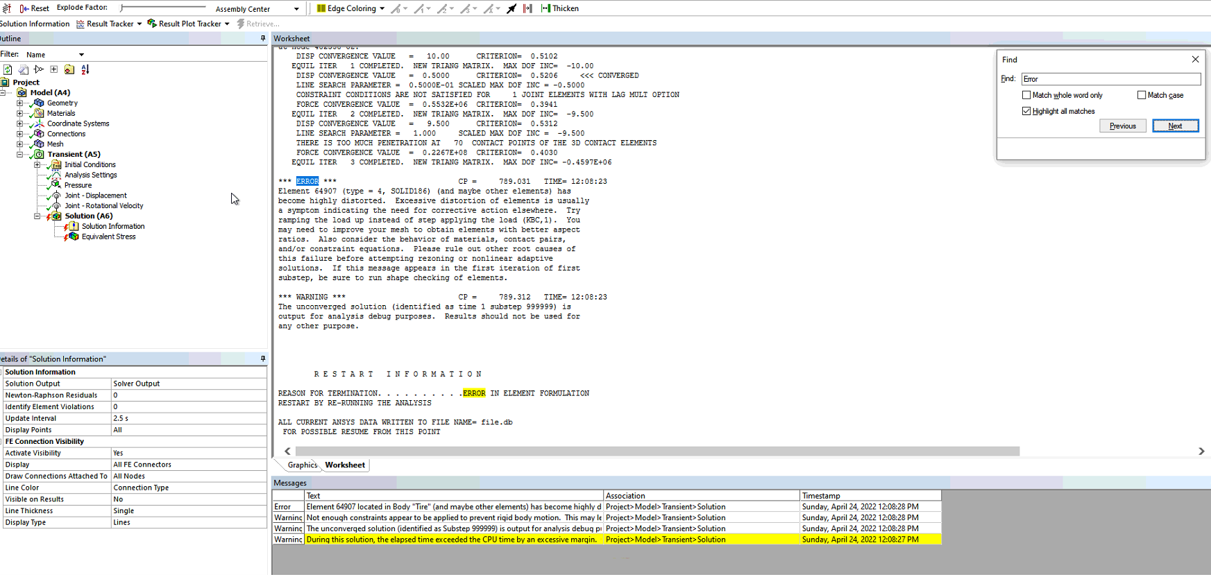
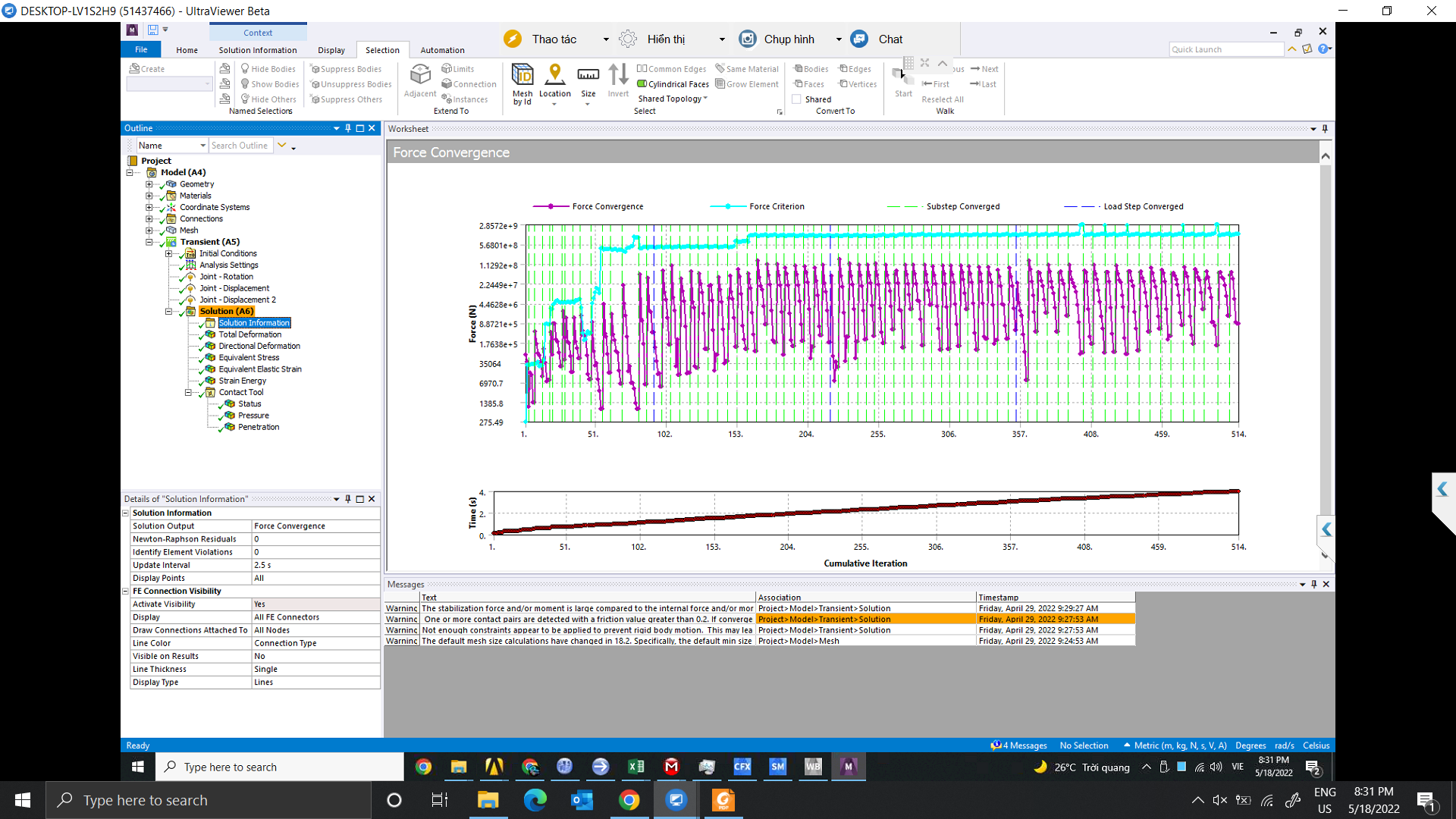
SubscriberFollow the advice in the error message. Click on the Solution Information Folder and look at the Solution Output and see what the error there says.
April 24, 2022 at 1:41 pmApril 24, 2022 at 11:17 pmpeteroznewman
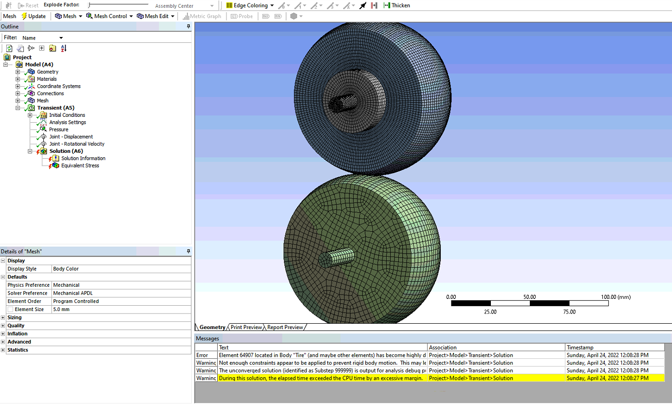
SubscriberThe mesh is fine. You can even use larger elements on the tire, use the same size as is on the drum. That will make the solution run a little faster.
I outlined a 4 step analysis. You have a problem with step 1 but I don't know if you have correctly applied the loads in steps 2 and 3 so they are not being applied in step 1. Therefore you have to show the tabular data for each load and show that the values are zero in step 1. The step 2 load is the Joint Translation. The step 3 load is Joint Velocity. Show that these have a value of zero in step 1. Once you know that, all you have to worry about is ramping on the pressure in Step 1.
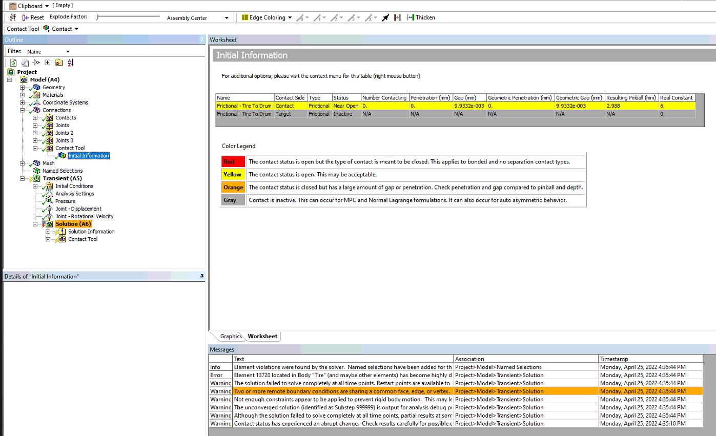
You also need to check the Frictional Contact. Insert a Contact Tool under the Connections folder. Evaluate the Initial Contact Status and check the amount of penetration. If it is excessive, then the tire and drum are overlapping in the Geometry program and should be moved until they are tangent.
In Mechanical, under Analysis Settings, make sure the Current Step is set to 1 and change Auto Time Stepping to On and set the Initial and Minimum number of Substeps to 100. This is what the text in the error message says to do. Also, make sure that Large Deflection is set to On.
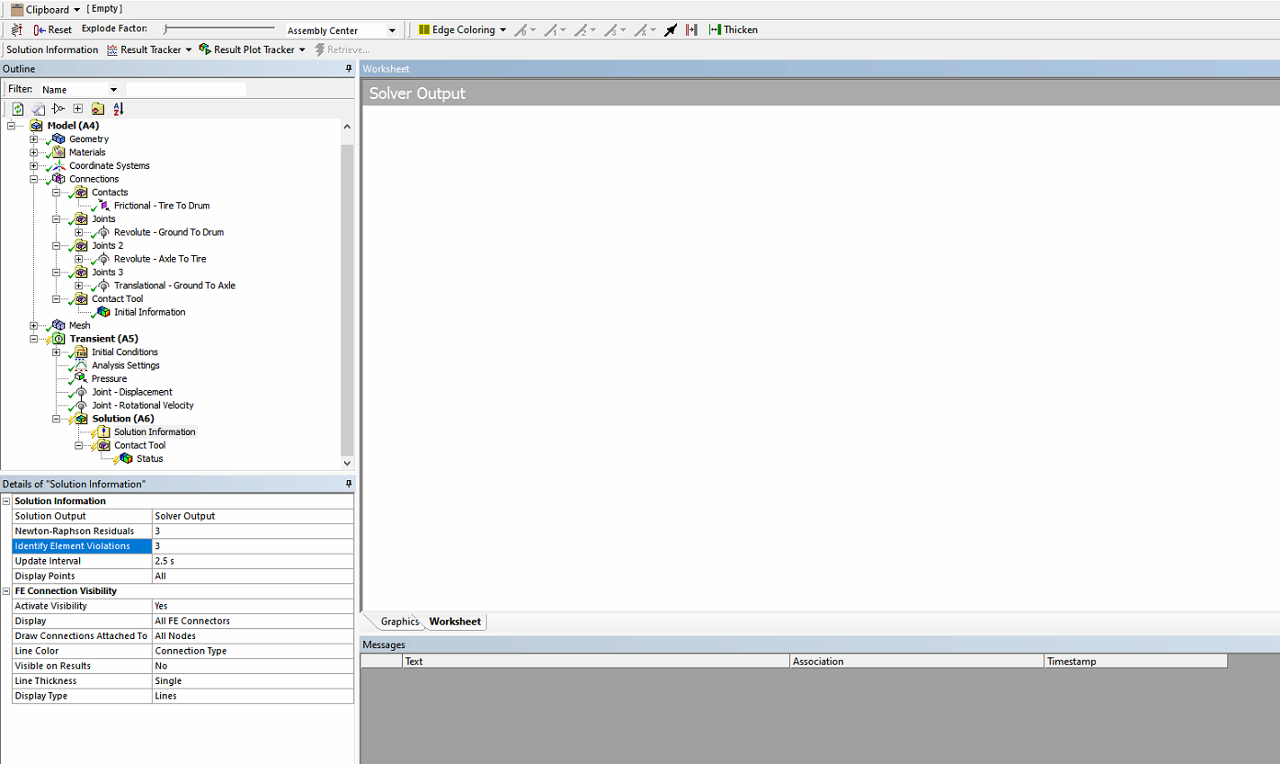
Under the Solution Information Folder, type a 3 in each of the two rows, one row says Newton-Raphson Residual Plot (or something like that) and the next row says Highly Distorted Elements (or something like that, I don't have ANSYS here). When you solve, a Named Selection will be created showing the Highly Distorted Elements.
April 25, 2022 at 9:32 amnguyenminhhieu15122000
SubscriberThank you for your support.
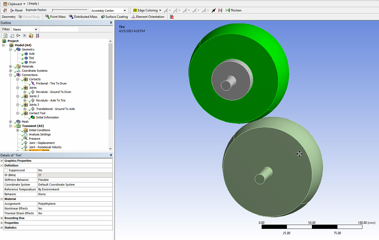
About the model, I draw them in contact with each other from scratch and during the test run, the contact status is displayed as shown below.
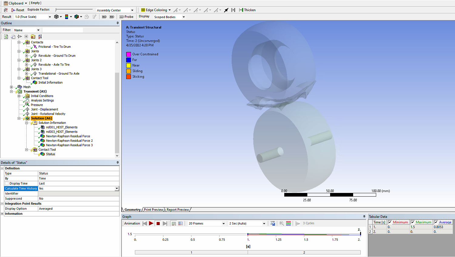 Can you help me check the steps again?
Step 1: End time 1, I increase pressure from 0 to 0.2 MPA
 Step2: End time 2, I increase displacement from 0 to 20 mm
 step 3: End time 4, I increase velocity from 0 to 10 rpm
 Analysis Settings
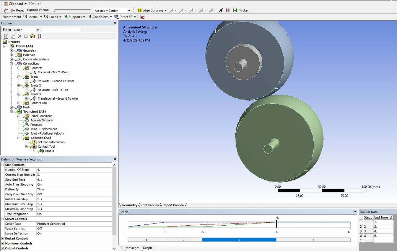 and I put 3 in each of the two rows
 About the material, I'm leaving the material for the tire as Polyethylene.
April 25, 2022 at 11:30 pmpeteroznewman
SubscriberInsert a Contact Tool under the Connections folder. You show a Contact Tool under the Solution folder.
The translation joint load of 20 mm is way too large! Try a 1 mm translation in the Y direction to press the tire on the drum.
The Translation Joint to Ground should be scoped to the small diameter axle surface.
The Revolute Joint on the Tire should be scoped to the large diameter surface on the axle.
The idea is each joint should have separate surfaces to hold on to. You don't want two joints sharing the same surface.
In Mechanical, under Analysis Settings, make sure the Current Step is set to 2 and set the Initial and Minimum number of Substeps to 100. Do the same for Step 3 and Step 4. Once you see good convergence, you might be able to reduce the number of substeps after you look at the N-R Force Residual plot.
April 26, 2022 at 2:26 amnguyenminhhieu15122000
Subscriberthank you for your support.
in the Joint Displacement, DOF is in the X displacement then let Y direction, will the tire move downwards?
this table in the contact tool under Connections
 and contact tool under the Solution folder
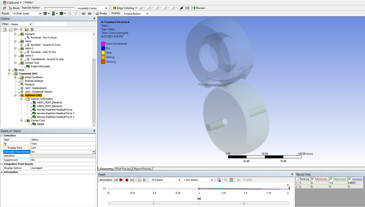 You can explain more in the section Analysis settings.
With current steps 2;3;4 then the Initial and Minimum number of Substeps to 100 then what is the maximum number? and current step 1 then still let Initial, Minumum, Maximum number of Substeps be 1;1;1
April 26, 2022 at 7:19 ampeteroznewman
SubscriberThe Translation Joint has a local coordinate system that has an X axis to move to tire toward the drum. That is the Global Y axis. That is what I meant.
Make all steps have an Initial and Minimum Substeps of 100 and a Maximum Substeps of 1000. These are conservative values and may cause the solution time to be longer than more optimized values. You can optimized the values once you have a solution that converges.
April 26, 2022 at 7:56 amnguyenminhhieu15122000
Subscriberthank you for your support.
I'm sorry for misunderstanding what you meant.
I tried changing the Analysis Setting this morning but it still leaves a question mark on the left side of the Analysis Setting
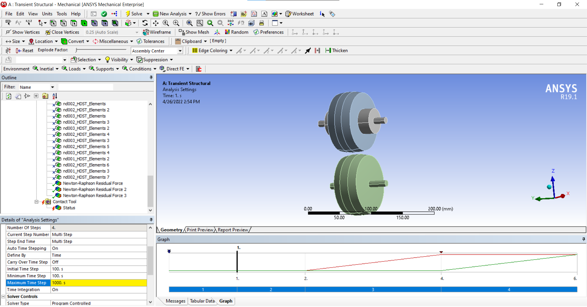 During the solution, I got an error displayed in the Message that: "element violations were found by the solver. named selections have been added for these elements." Besides, I still haven't figured out how to fix the Element
April 26, 2022 at 5:25 pmnguyenminhhieu15122000
SubscriberThank you very much for your help.
Now, I have run the problem and will send the video for your comment tomorrow.
I have a question. With the use of this model, the problem does not need to use vertical forces but only needs to move the axle of the tire close to the drum thereby generating heat, right?
April 27, 2022 at 6:38 amnguyenminhhieu15122000
SubscriberCurrently my tire and drum are not in contact with each other. Is the spacing between them related to the Contact Tool - Initial Information section.
I want to make the tire and drum rotate more, can I increase the number of steps, sir?
April 27, 2022 at 7:41 ampeteroznewman
SubscriberI thought the geometry was configured so the tire and drum were tangent in the Geometry program. The video shows them with a huge gap. Make them tangent.
The first 2 steps, Pressure and Movement should be done with Time Integration turned Off. Define Automatic Time Stepping by Substeps, not Time. That is what I was suggesting above. The end time of step 1 is 1 second. The end time for step 2 is 2 seconds. Step 3 is when Time Integration is turned On.
April 28, 2022 at 4:31 amnguyenminhhieu15122000
Subscriberthank you for your support.
I edited the drawing so that the tire and drum are a little further apart. My idea is that the tire has an initial velocity, then move the tire down the drum with zero rotational velocity.
I am using Joint - Rotational Velocity to set up the tire. I am wondering, should I use velocity for tires or Rotational Velocity.
April 28, 2022 at 4:52 ampeteroznewman
SubscriberWhat is the logic behind your idea that the tire has an initial velocity and the touches down on a stationary drum?
The opposite arrangement, where the drum is spinning and the stationary tire touches down, would simulate the loads an aircraft tire sees on touchdown.
I thought you wanted to study the heat build-up when the tire is rolling. The model is built with two revolute joints, one on the drum and one on the tire. Either one can have a Joint Load, Type = Velocity to drive rotation, but not both. The other one can have a Joint Load, Type = Moment to simulate rolling resistance.
April 28, 2022 at 8:29 amnguyenminhhieu15122000
Subscriberthank you for your support.
I think going to two Type=Rotation Velocity.
Tire will have an initial rotational velocity. When the Tire is in contact with the Drum, the Drum will rotate, we can set the rotation speed of the Drum when the contact starts.
May I do that, sir?
I want the tire to have a speed of km/h but in Type=Rotational Velocity it has rpm.
April 28, 2022 at 11:07 ampeteroznewman
SubscriberIt's your model, you can do as you please.
I wrote what I would do: use one Joint Load, Type = Rotational Velocity, the other Joint Load can be a small value of Moment to represent bearing friction.
The tire comes into contact with the drum before any rotation begins in Statics solution (time integration OFF). Then in Step 3, time integration ON and the rotation ramps up from 0 to a constant value, then in step 4 continues at a constant value.
How will you create an initial rotational velocity?
Since you know the diameter of the tire, you can convert km/h to rpm.
April 29, 2022 at 3:57 amnguyenminhhieu15122000
Subscriberthank you for your support
I am running ansys workbench 2020R2, coupled Field Transient model and i am getting this error "rigid bodies are supported for bodies with pure structural physics"
I use the material of the tire is Rubber, and the material of the Drum and Axle is Structural Steel.
April 29, 2022 at 7:53 ampeteroznewman
SubscriberDon't use any Rigid Bodies for a coupled field transient analysis.
May 4, 2022 at 1:14 amnguyenminhhieu15122000
SubscriberThanks for your enthusiastic help. I did the exercise as I wanted.
May 4, 2022 at 1:28 amnguyenminhhieu15122000
SubscriberDear Sir,
After completing the above problem, I am doing an exercise to simulate the heat that accumulates in the rubber layer of a tire.
I have chopped up the models and assumed their material is rubber.
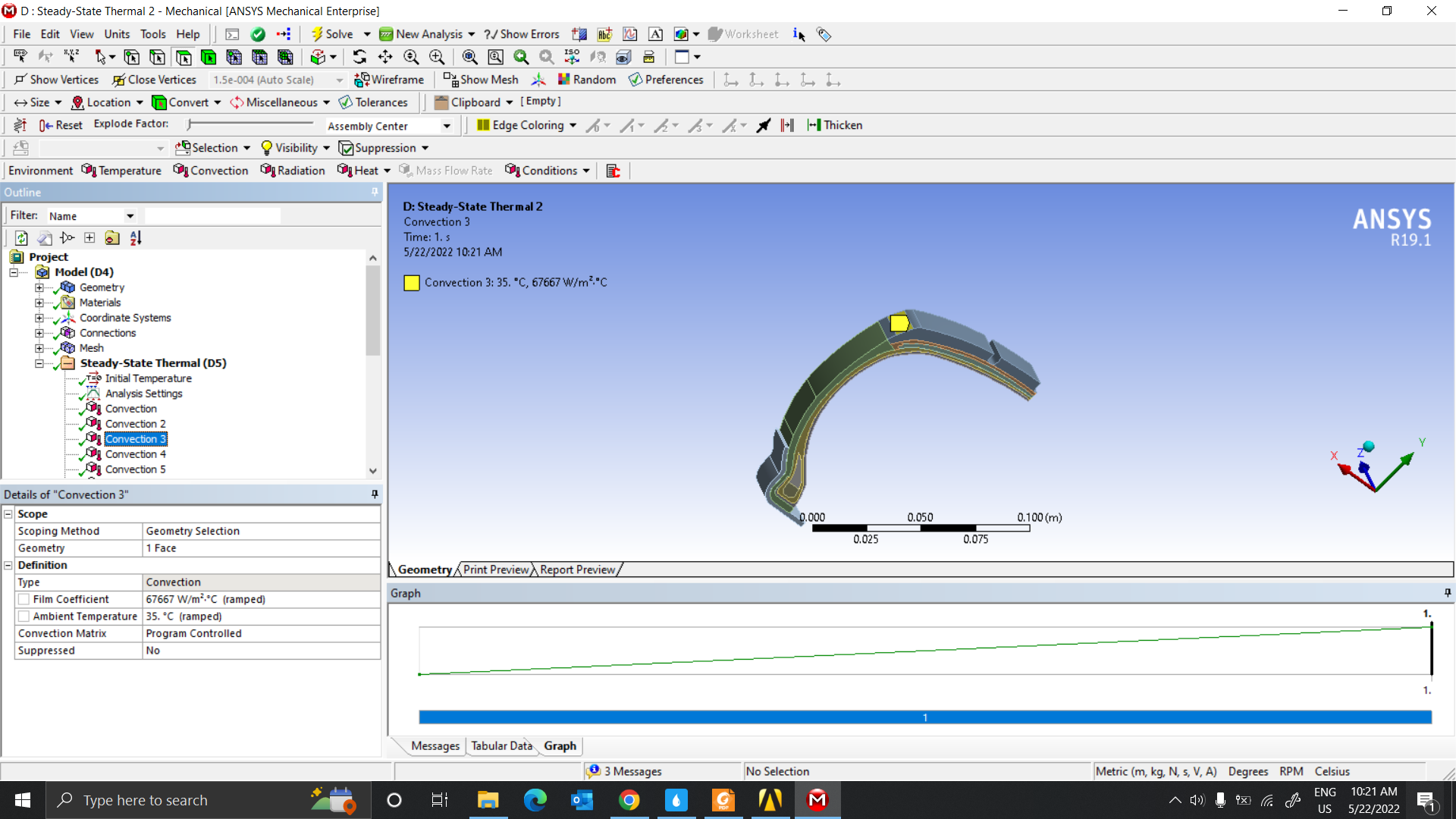
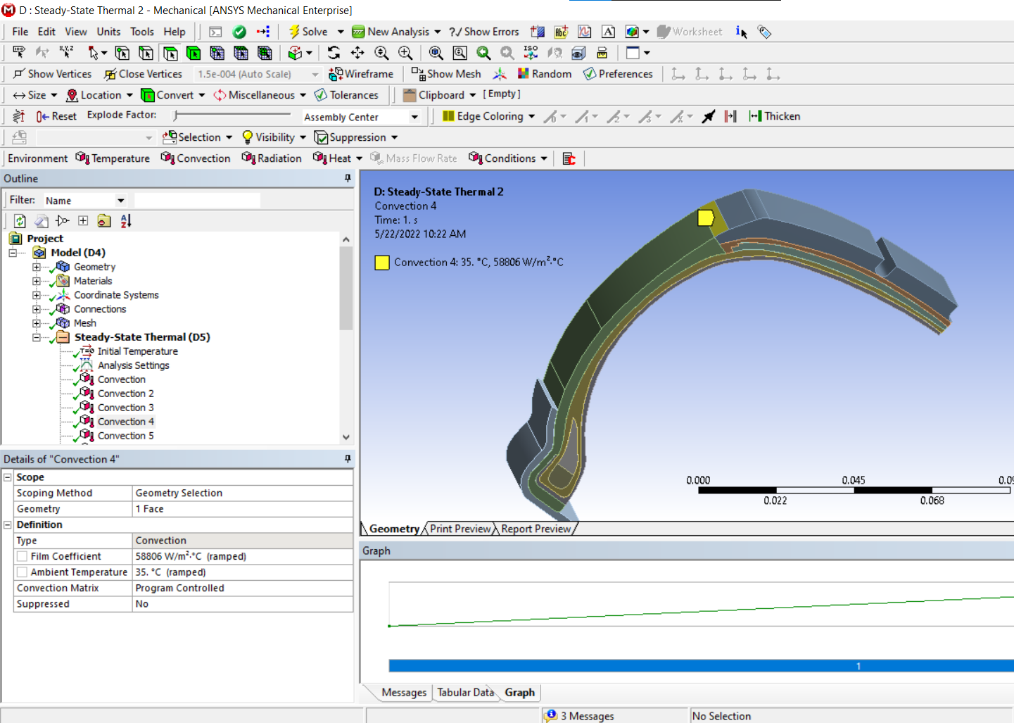
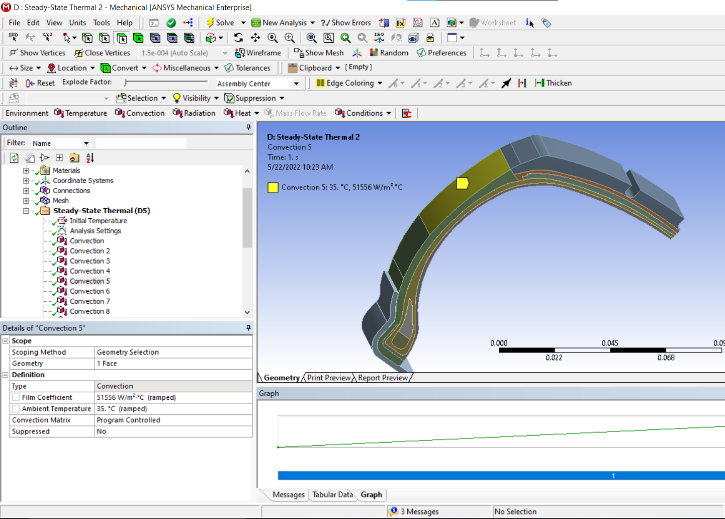
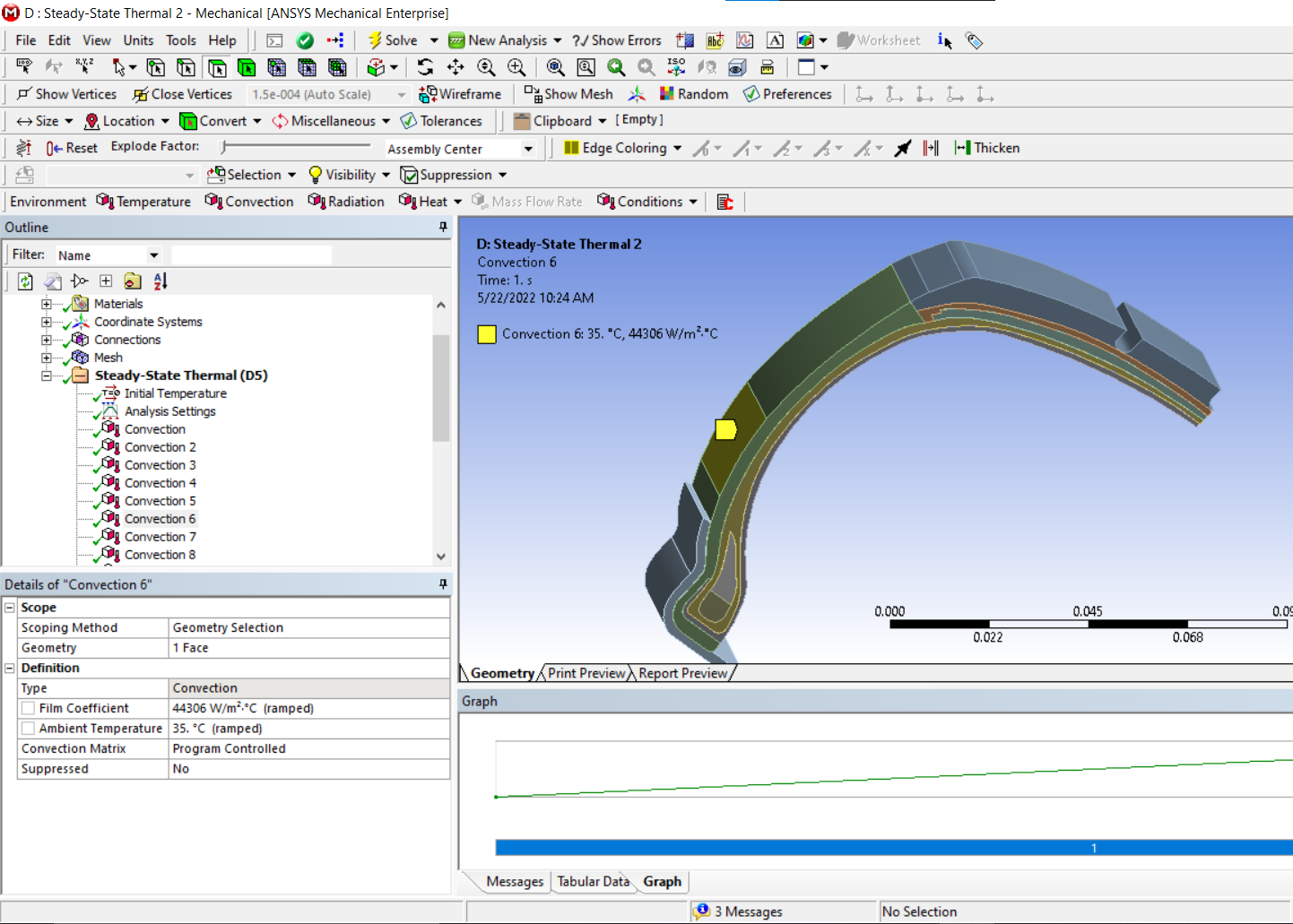
I am using the model Steady-State Thermal, however, the end result was not as expected. Looking forward to hearing from you.
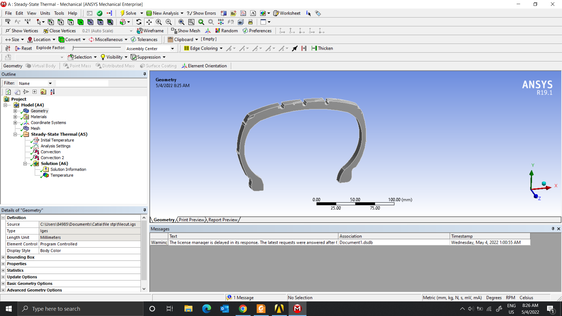
May 4, 2022 at 3:48 pmpeteroznewman
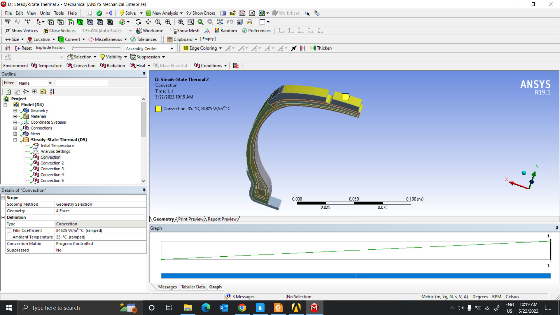
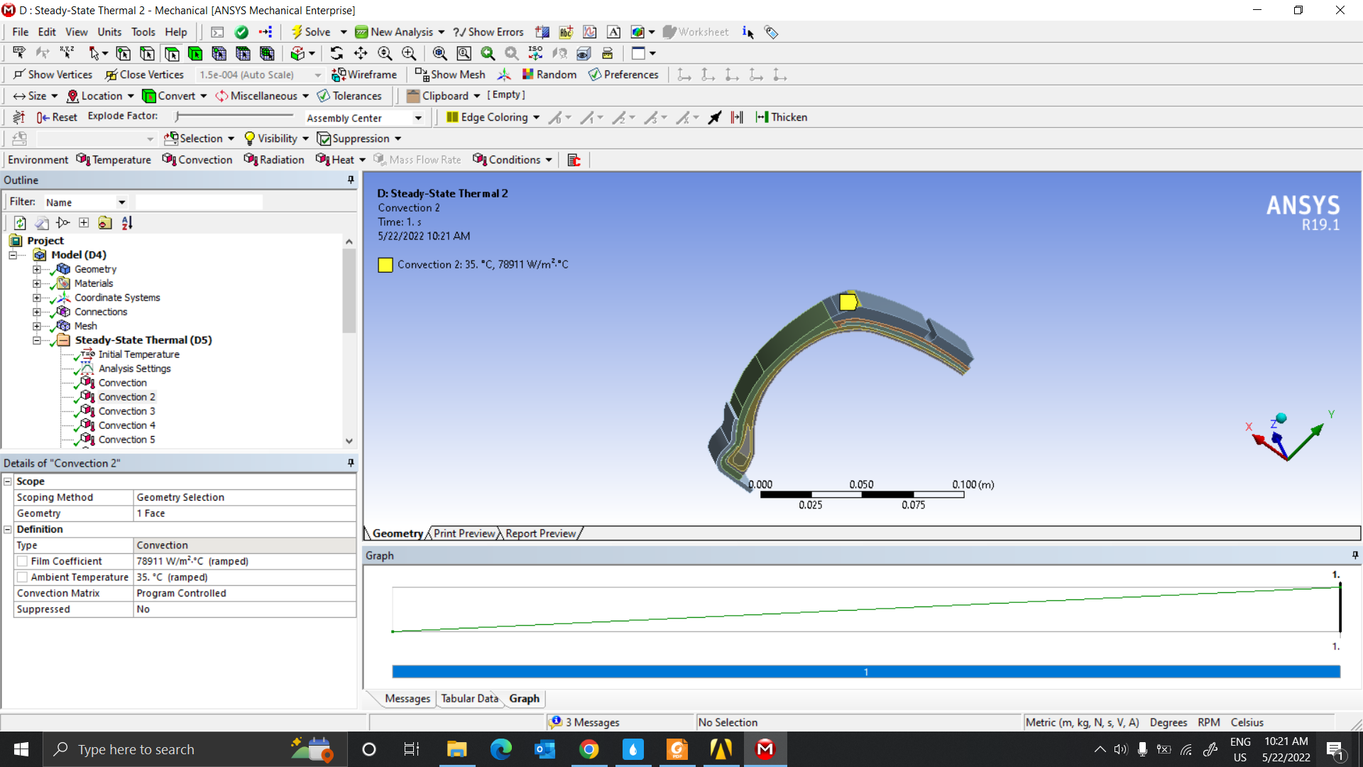
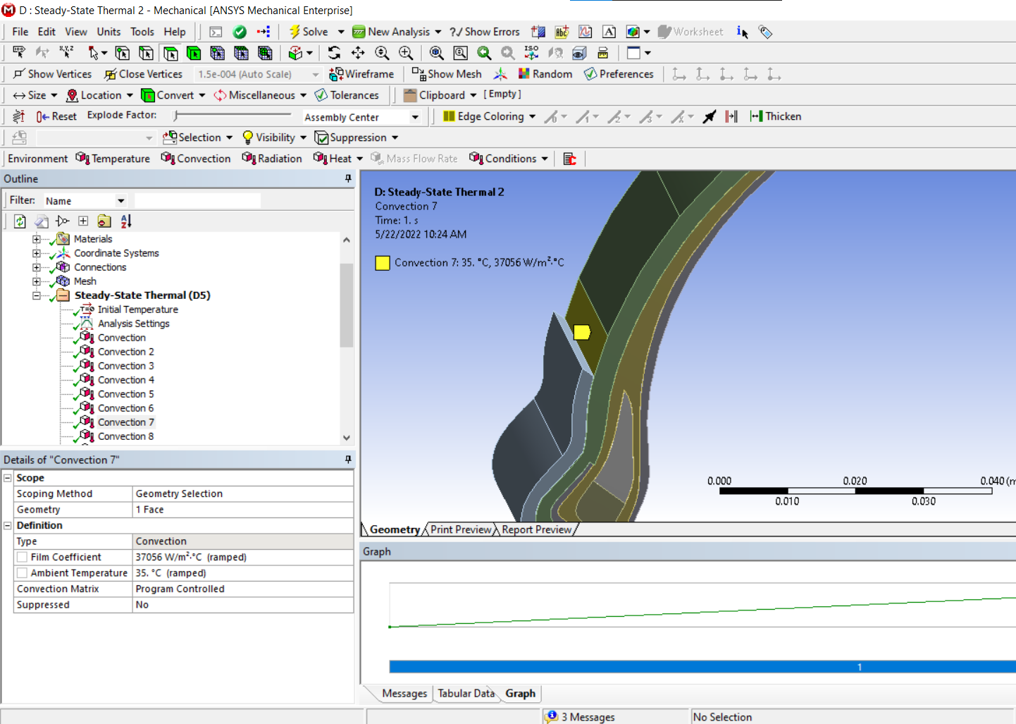
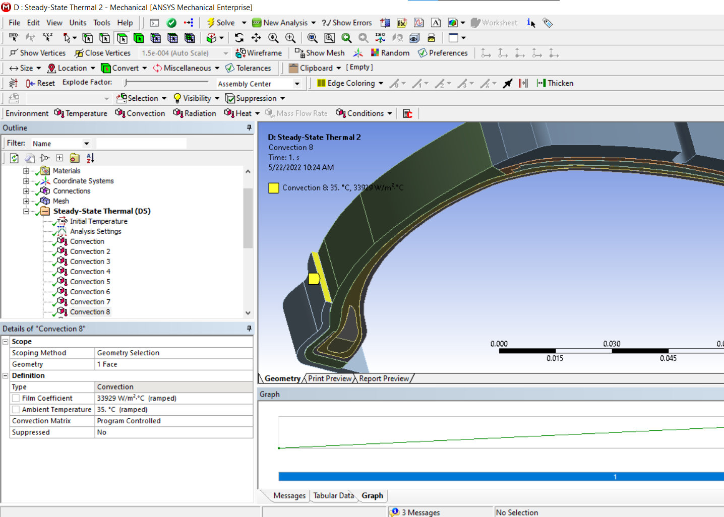
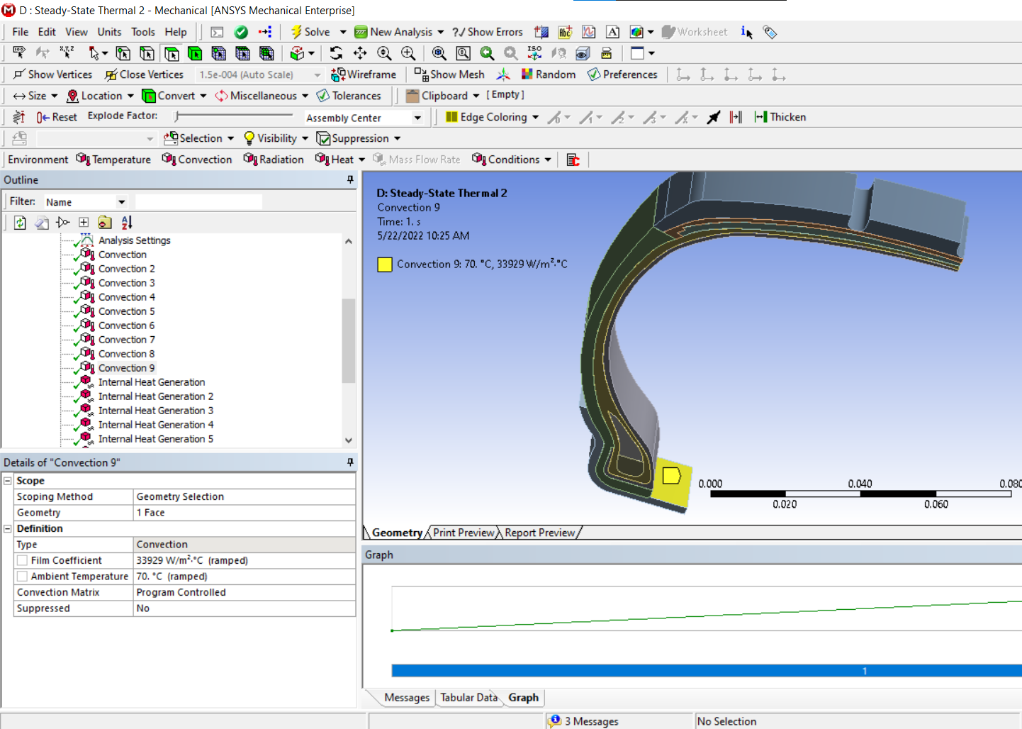
SubscriberWhat are the Details of each Convection load, where did you get the inputs for them, and what surfaces are they applied to?
What did you expect to get?
May 5, 2022 at 12:19 pmnguyenminhhieu15122000
SubscriberAs far as I find out, the rubber part is the part in contact with the road surface, it affects the stiffness of the tire. So I want to see the temperature distribution of this rubber part. Thereby, it is possible to think of improvement options.
I am referring to the article below and trying to apply it with the Steady State model like the image above. However, the object above is a body. I'm referencing the article below and currently applying it. I'm working on drawing parts using rubber in tires.
Looking forward to your suggestions. Thank you very much
May 9, 2022 at 1:59 pmnguyenminhhieu15122000
SubscriberLooking forward to your help again.
May 9, 2022 at 2:28 pmpeteroznewman
SubscriberOkay, what problem do you have building a model to reproduce what was in the paper?
May 9, 2022 at 3:08 pmnguyenminhhieu15122000
Subscriberthank you for your support.
I want to simulate the temperature field of the tire components that are made of rubber.
According to the previous directions, I use Structural models such as Static Structural or Transient Structural, .. to simulate.
Right now, I'm working with thermal modeling. I have referenced the above article and am practicing following it.
About the model, i'm drawing just like the photo and in the article and assuming they have a rubber material
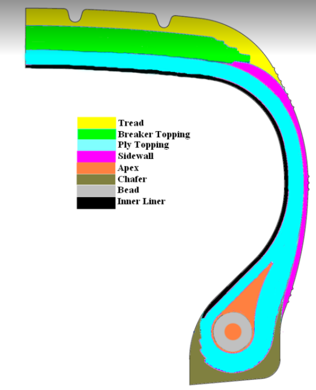 Regarding the condition settings, I haven't determined how so I would like to ask for your opinion.
In the article, they mentioned conditions like Heat Convection Coefficient and Heat Generation Rate (but I don't know which setting this corresponds to in the Steady State Thermal model).
May 9, 2022 at 3:26 pmpeteroznewman
SubscriberHave you taken the relevant free courses?
/courses/index.php/courses/heat-transfer-learning-track/
/courses/index.php/courses/3d-conduction/
/courses/index.php/courses/topics-in-heat-transfer-analyses/
May 9, 2022 at 3:36 pmnguyenminhhieu15122000
SubscriberI have not joined it and I will watch it the next day.
Regarding the problems I am facing, is my presentation easy to understand, sir?
May 9, 2022 at 6:31 pmMay 10, 2022 at 1:58 amnguyenminhhieu15122000
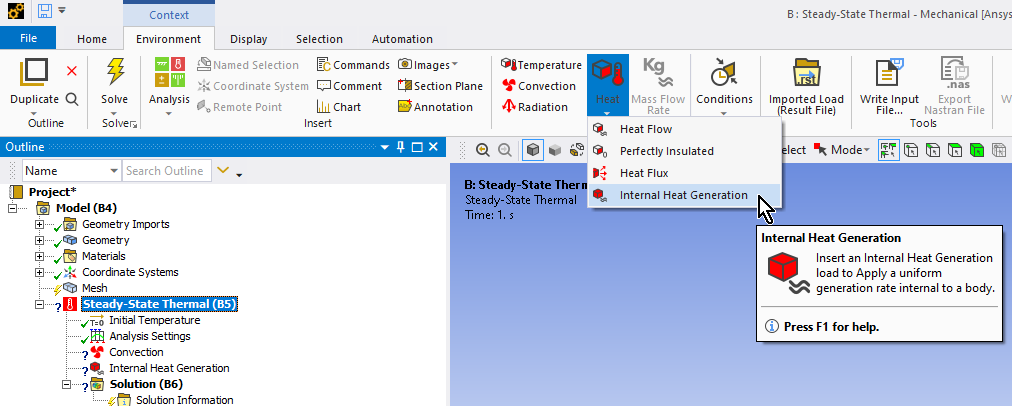
SubscriberI know the location of heat convection. As for heat generation, if I choose internal heat generation, I will only be able to select All Bodies, not one by one, so I'm wondering there, Sir.
May 10, 2022 at 7:40 amnguyenminhhieu15122000
SubscriberAh sorry sir, because I use the undivided model so I can't choose.
May 10, 2022 at 10:28 ampeteroznewman
SubscriberOpen the geometry in SpaceClaim. Use separate bodies for each color. On the Workbench tab, use the Share button to connect the mesh across bodies with coincident faces.
It would be much simpler to have a flat radial surface to carve up than solid bodies.
May 10, 2022 at 3:51 pmnguyenminhhieu15122000
SubscriberThank you for your support
Can you help me check?
I draw the simple components of the tire.
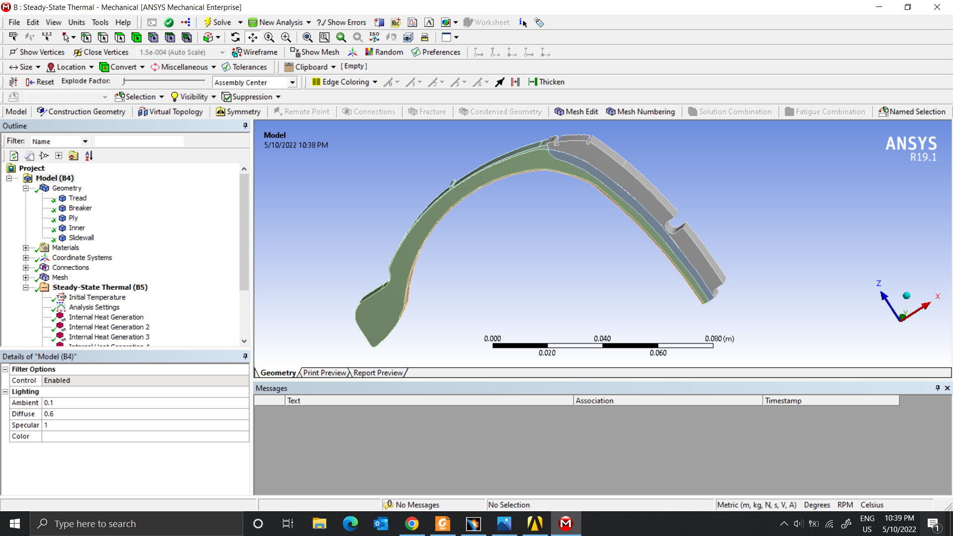 Meshing.
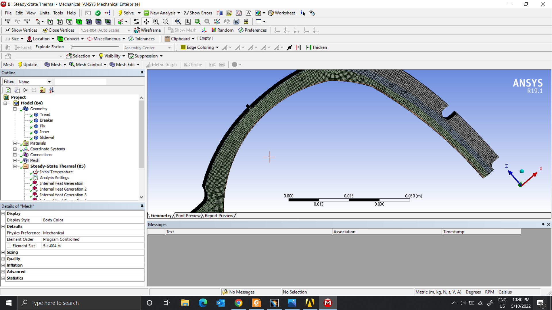 I use the input condition parameters as Heat generation(Heat rate) and the temperature of the inner surface of the tire was defined as 60┬░C, and the temperature of the outer surface was defined as 20┬░C.
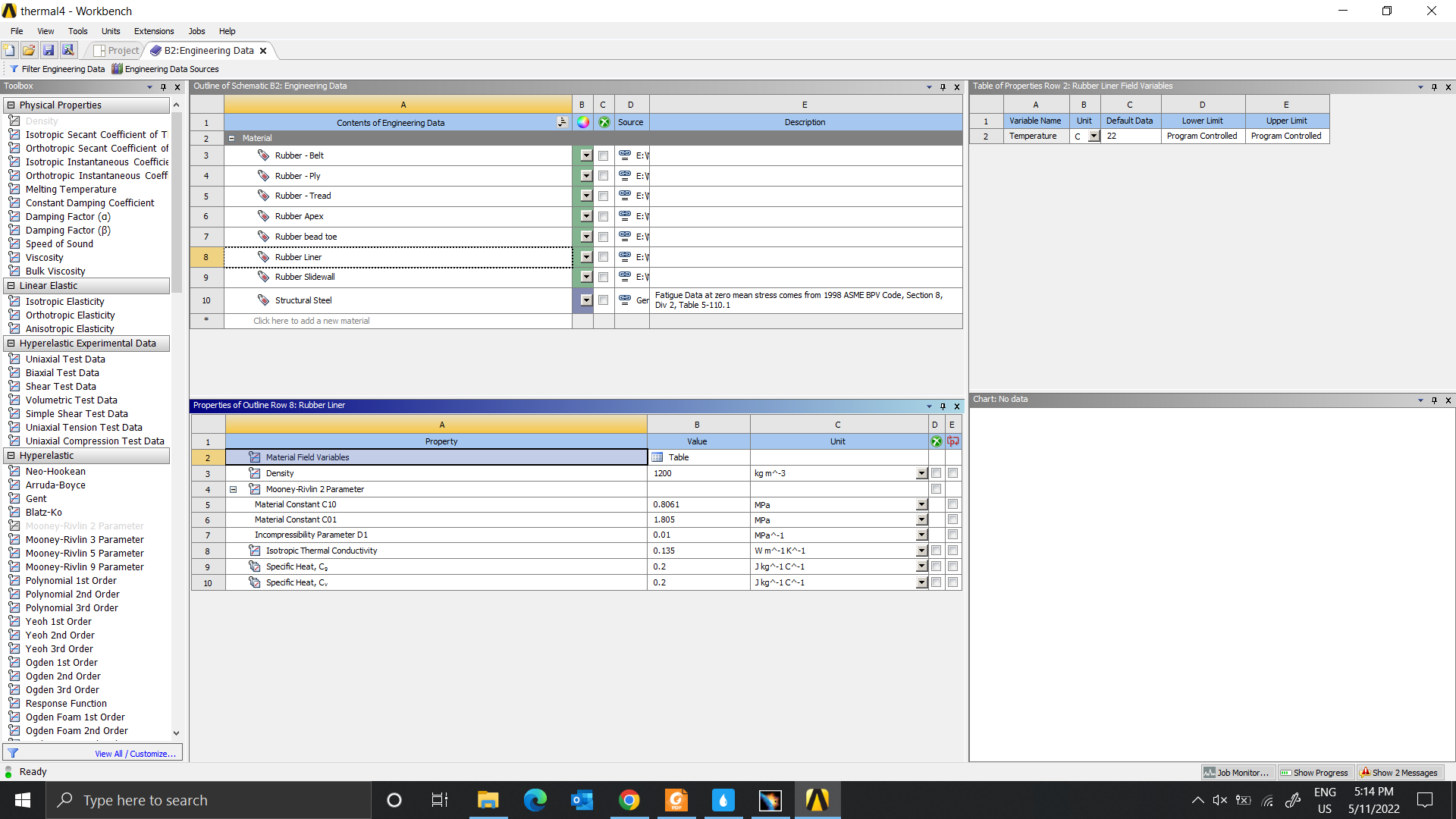
I used rubber material, duplicated it several times and corrected the Thermal conductivity parameter according to the table below
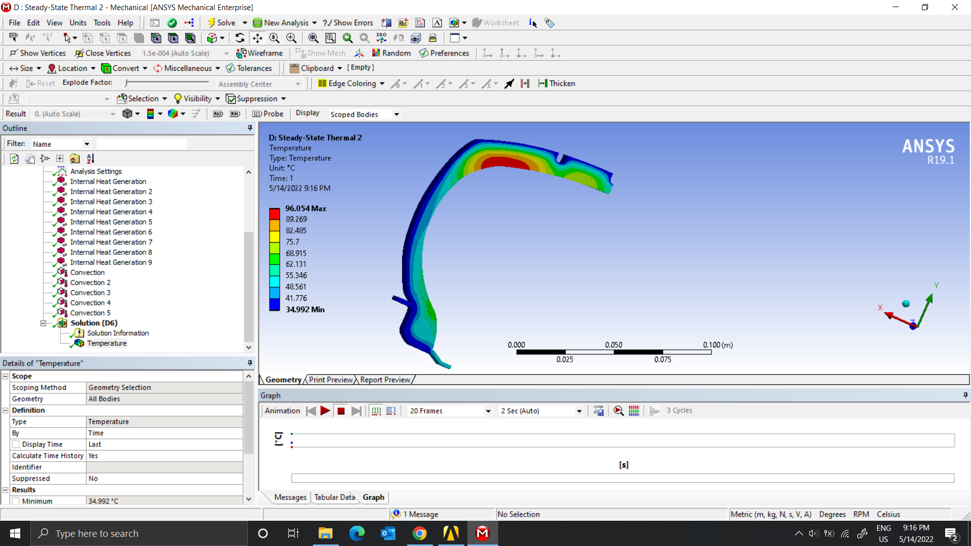
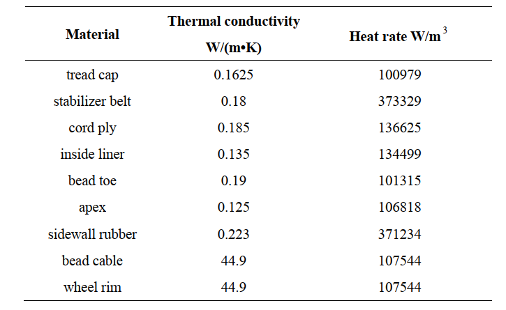 Here are the results
 Thank you again.
May 10, 2022 at 5:26 pmpeteroznewman
SubscriberThe paper used Convection BC on the inside and outside of the tire. You used a Temperature BC on those same surfaces. That is not the same.
May 10, 2022 at 6:24 pmnguyenminhhieu15122000
SubscriberYes, Sir. I used Temperature BC instead of Convection BC.
Because I'm not sure the formula the paper gives.
Some other articles pointed out that " convection coefficient was applied at the outer surface by 5.9 + 3.7 ╬¢ W/m2 ÔùªC (╬¢ is the air speed in m/s)"
I'm wondering here, Sir
May 10, 2022 at 8:15 pmpeteroznewman
SubscriberDon't use a Temperature BC if you are following the example in the paper. Use a Convection BC. That has two inputs, the coefficient and the ambient temperature of the air.
May 11, 2022 at 1:11 amnguyenminhhieu15122000
SubscriberI know those 2 conditions. I will try again
May 11, 2022 at 8:29 amnguyenminhhieu15122000
SubscriberI have 2 questions to ask you
- As for the Analysis Settings, it should be left as reasonable (I'm leaving
- About the parameters of the material, since the article does not provide them, I am using the data of another paper. Have you worked in this field, if you have, would you please suggest which parameters to use?
Thank you very much
May 11, 2022 at 9:45 ampeteroznewman
SubscriberDefault Analysis Settings should be fine.
Which material properties are you asking about?
May 11, 2022 at 10:14 amMay 14, 2022 at 9:44 amnguyenminhhieu15122000
SubscriberSince the previous article did not provide the material's parameters, I chose another paper for validation.
However, this article is using software called Abaqus, so I have some problems that you suggested.
In this article, they combine both thermal and structural, so I think I will use the Coupled Field Static or Coupled Field Transient model for this problem. Here, I am stuck on how to set load and velocity conditions. Hoping for your help. Thank you again.
May 14, 2022 at 10:34 ampeteroznewman
SubscriberIt seems your goal is to reproduce a simulation found in a paper. You should choose a paper that has a simpler simulation. The second paper is simpler than the first or the third papers you reference. You started a model from the first paper and abandoned it, you started a model from the second paper and nearly finished it, and now you propose abandoning that to start a third model, which would be more complicated. I suggest you complete the second model. It seemed all you needed was to change the Temperature BC to a Convection BC. You found a paper that gave a formula for the convection coefficient. Why don't you use that?
May 14, 2022 at 2:21 pmMay 14, 2022 at 2:26 pmpeteroznewman
SubscriberIt looks like you have a model that reproduces the results of the second paper. How are you stuck? Aren't you finished?
May 14, 2022 at 4:41 pmnguyenminhhieu15122000
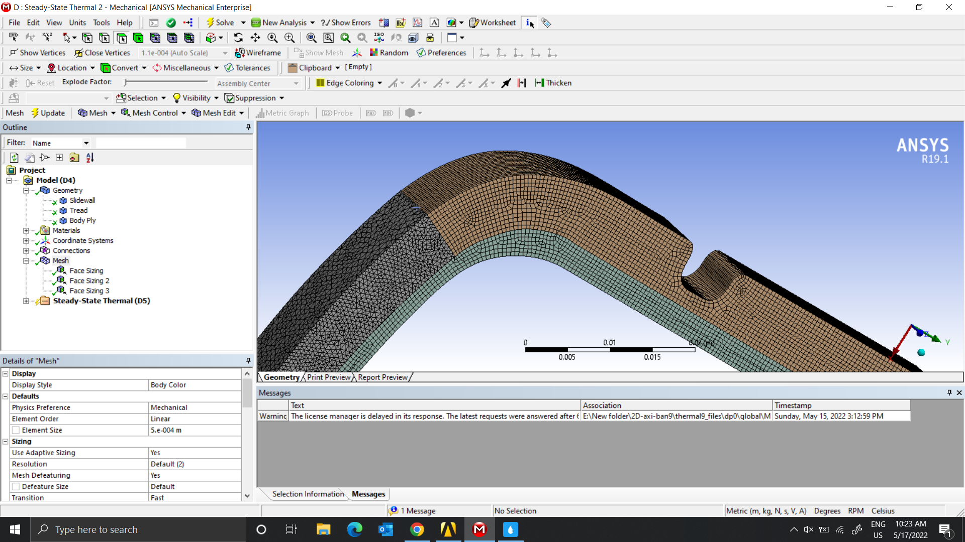
SubscriberIn the 2nd paper, Regarding the model, there is a slight change from the model of the paper. I think it may be due to not having the exact material that my problem is not correct. I can say that I haven't finished the simulation yet. So I'm trying with the 3rd paper.
In the 3rd article, they only need the tread, body ply, and Slide wall parts to serve the simulation(more clearly they cut the upper part).
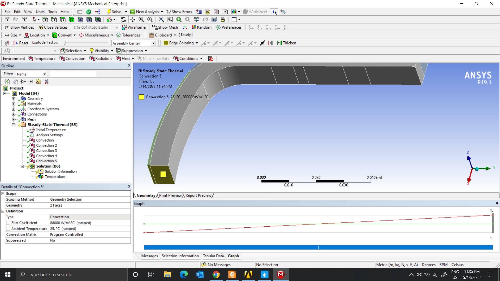
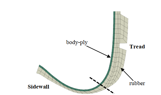 This is the boundary condition part
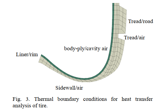 And here are my settings.
Tread /road
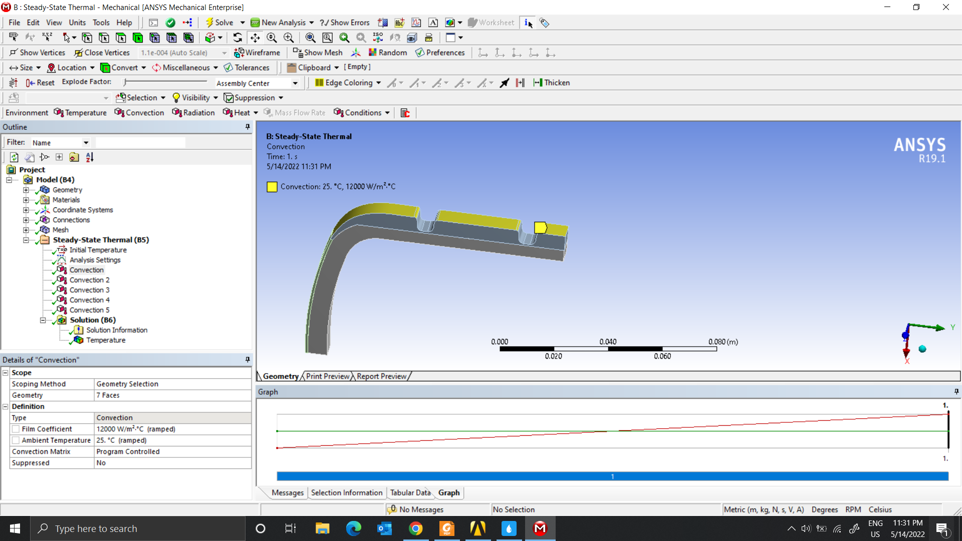 Slide wall/Air
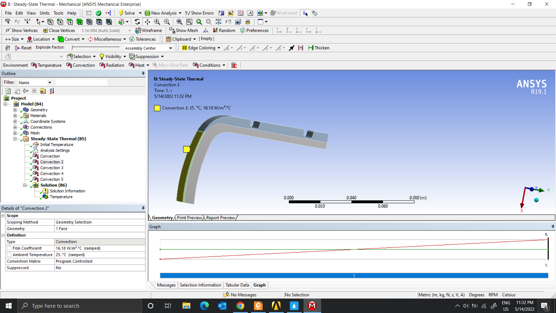 Tread/Air
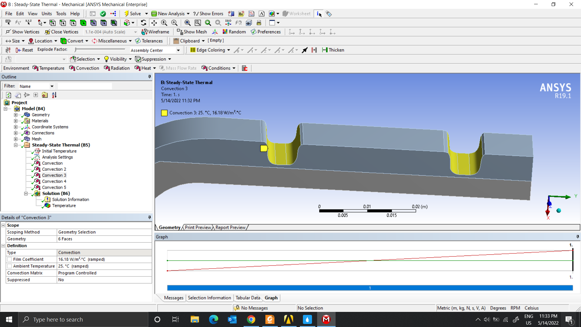 Body Ply/cavity air
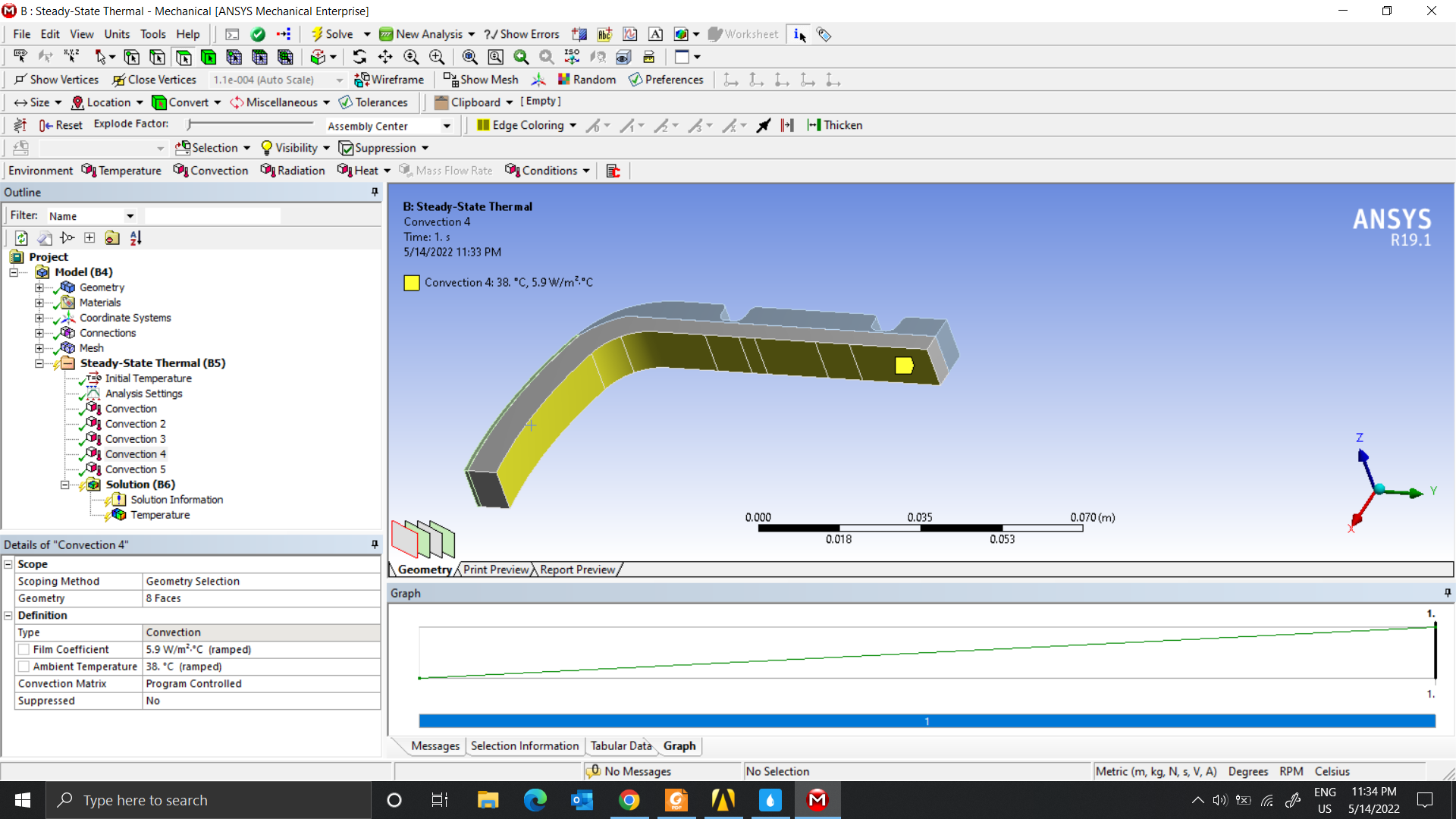 Liner/Rim
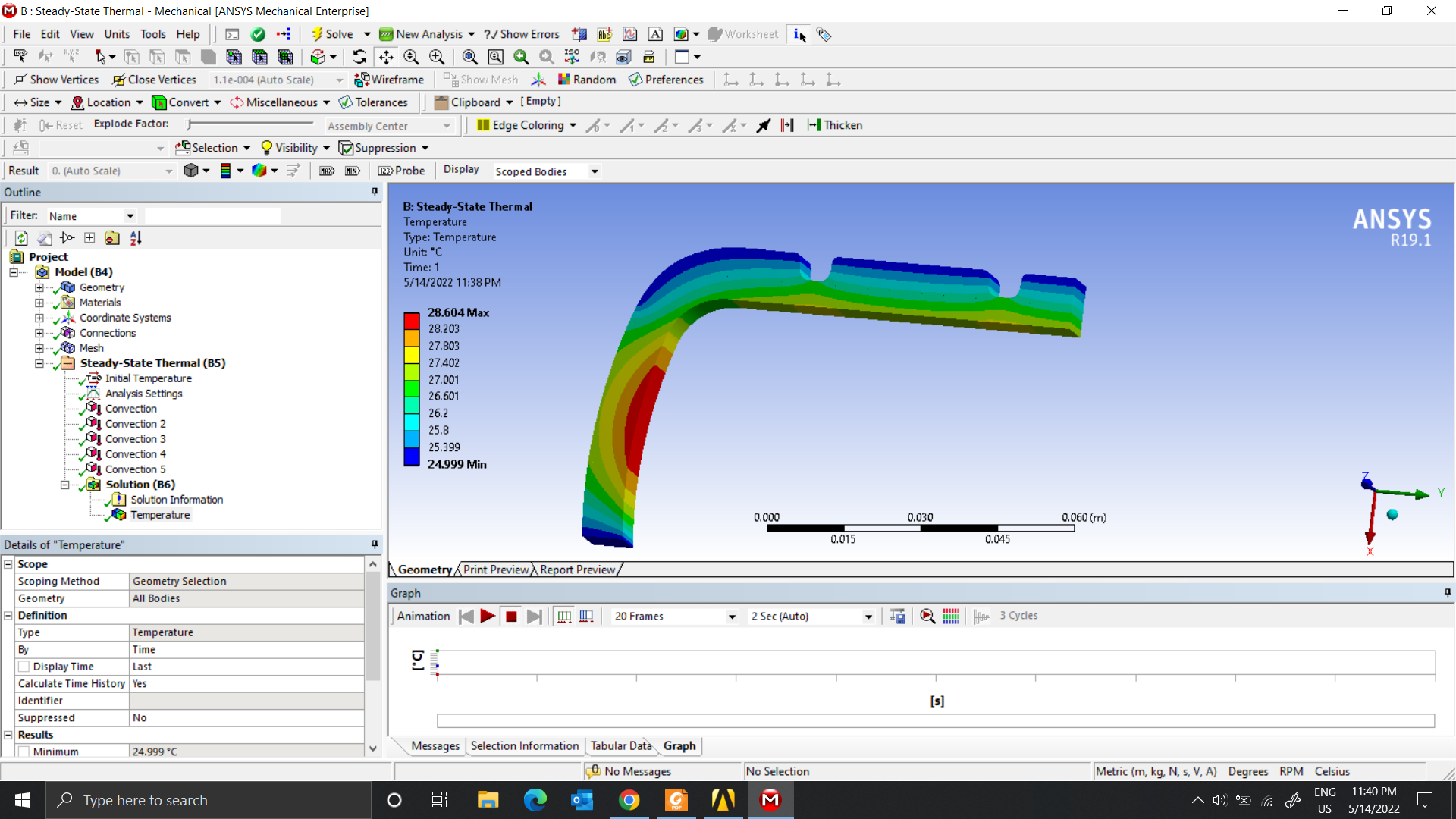
 About the results, my simulation is wrong. I think it will have the most heat under the tread, not the side of the Slide wall.
 Thank you so much for helping me.
May 14, 2022 at 9:25 pmpeteroznewman
SubscriberYou haven't added the Internal Heat Generation from the 2nd paper. They don't need that in the 3rd paper because the get that from rolling the tire and the deformation of the rubber generates the heat.
May 15, 2022 at 1:36 amMay 15, 2022 at 5:21 pmnguyenminhhieu15122000
SubscriberCan you help me again? Sincerely thank you very much.
In the 3rd paper, after exporting the results of the thermal model, I saw that they annotated the image with the appearance of force F, pressure, and velocity (constant). Because the article is done with Abaqus software, but I use it with Ansys software, Steady State Thermal model, the above conditions cannot be added. So should I use the Coupled Field Static model or not, and please show me how to set the force and velocity conditions for the structural model
May 15, 2022 at 9:44 pmpeteroznewman
SubscriberThe results you show above reproduces the methodology in the 2nd paper. Do you need to reproduce the 3rd paper also? That will be a lot of extra work.
May 16, 2022 at 2:11 amnguyenminhhieu15122000
SubscriberCurrently, I just need to follow the steps exactly as shown in the paper.
After I do exactly as in the paper, I will think more about the reconstruction later.
Thank you for your help.
May 16, 2022 at 10:29 ampeteroznewman
SubscriberThe 3rd paper generates heat by rolling the tire, like the first model you were building.
The 2nd paper uses Internal Heat Generation, avoiding the need to have a rolling tire.
To make a model that follows the 3rd paper, you would need to have a rolling tire and a material model that generates heat as a function of deformation.
May 16, 2022 at 2:15 pmnguyenminhhieu15122000
SubscriberThank you very much for your help.
In your opinion, in the second paper, is it because the model I drew is different from the model in the article or the wrong material parameters lead to incorrect results?
In the 3rd paper, I am not sure how to set the force and velocity at the center of the tire, hope you can elaborate.
Please explain more, because I see they use different models for each case, like using axis-symmetric cross-sectional for thermal modeling and 3D modeling for structural modeling. So if I use 3D model, combine the conditions of both thermal and structural models, the result will still be the same, right?
May 16, 2022 at 4:04 pmpeteroznewman
SubscriberYou will only get identical results to the 2nd paper if you use identical geometry, material properties and boundary conditions.
The 3rd paper uses a material model that generates heat as a function of deformation. You need to figure out how to do that in ANSYS. I suggest you build a very simple model of a unit cube and mesh it with one linear element with eight nodes. Use symmetry on 3 planes to hold the element in place. On one of the free faces, apply a displacement on the 4 nodes to compress the unit cube by 0.1 in step 1 and then return to 0 displacement in step 2. When you can show a temperature increase in this model at the end of step 2, you are ready to tackle another piece of the 3rd paper.
May 16, 2022 at 4:52 pmnguyenminhhieu15122000
Subscriberthank you for your support.
In fact, I prefer to do the 2nd paper because it is simpler. However, the article did not provide material specifications which prevented me from doing exactly the same as the paper.
In the 3rd paper, according to your instructions. It looks more complicated than I thought. I am using with real tire model, cutting them and drawing the tire components to simulate, but the result is not accurate
May 16, 2022 at 6:05 pmnguyenminhhieu15122000
SubscriberDear Sir Actually, I found this article first and also my first direction. However, I would like to find more recent articles for validation.
Maybe I was wrong, so I will choose this paper again. Since It's done using Ansys Software
In this paper, they also model with eight nodes elements. I'm not very clear on this concept, hope you can guide me further.
Next about the thermal model, Still an old problem, I am mistakenly thinking that they use Steady State Thermal model, but their results refer to pressure, force, and velocity which in Steady State model does not have the conditions in this case.
Thank you for your support.
May 16, 2022 at 7:55 pmpeteroznewman
Subscriber8-node elements are created when you set the Element Order under the Mesh category to Linear and mesh six-sided solid bodies. You will get hexahedral-shaped elements with one node at each corner.
May 17, 2022 at 3:26 amMay 17, 2022 at 8:47 amnguyenminhhieu15122000
SubscriberDo you mean Mechanical APDL? So if I want to work on the models that I often use, is It possible?
I hope you can guide me more clearly because it's my first time approaching this concept
May 17, 2022 at 10:14 ampeteroznewman
SubscriberThe gray body is meshed with tetrahedral elements. Right click on the Mesh branch of the outline and select Show Sweepable Bodies. Does the gray body highlight in green? If so, that can be meshed with hexahedral elements by adding a mesh control called a Method, Sweep. If the shape of the gray body is a triangular prism, the sweep can be between the triangles (Source and Target) or between the rectangles on each cut face. The element size you show is much smaller than the element size shown in the paper which use larger element sizes (fewer elements).
The simple one element model can be built in Mechanical/Workbench. I don't know if you will need to use any APDL command snippets to achieve the heat generating material model. That remains to be seen.
May 17, 2022 at 10:46 amnguyenminhhieu15122000
SubscriberI select Show -> Sweepable Bodies and it highlights in green.
Next, I choose Method->Sweep and get the information panel below.
How should I choose Source and Target?
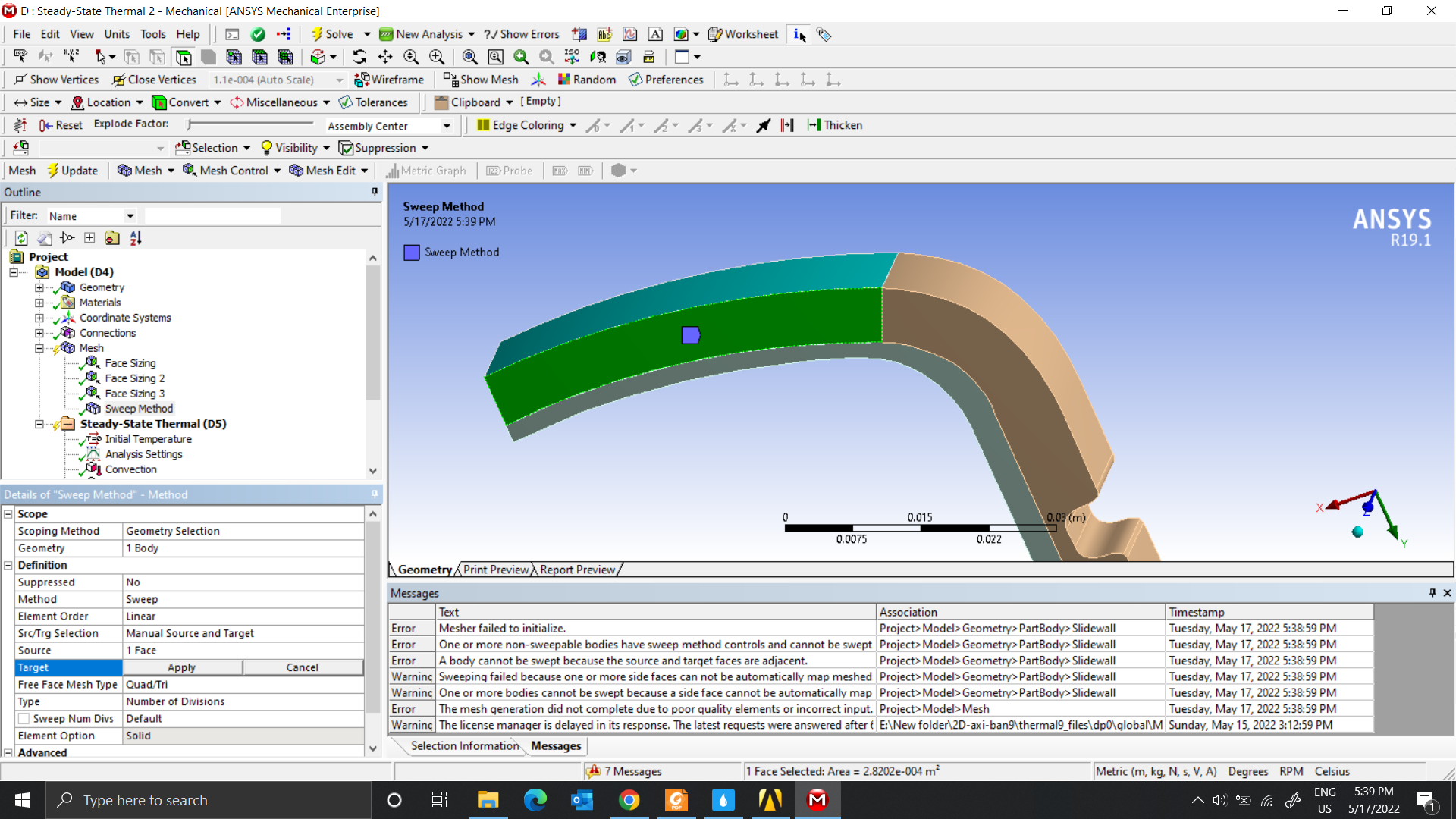 If I choose Src/Trg Selection => Automatic, the Mesh will look like this
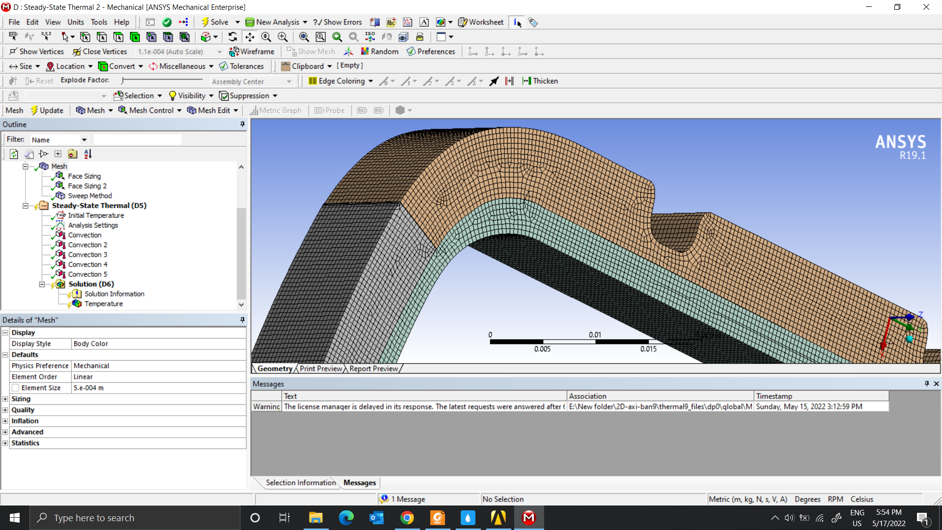 In the last paper I sent you, they used Ansys/Mechanical for thermal analysis.
So according to you, I should choose which model will be suitable.
May 17, 2022 at 11:08 amnguyenminhhieu15122000
SubscriberDear sir, can you help me model the tire by eight-node 3D elements?
May 17, 2022 at 11:38 ampeteroznewman
SubscriberNow you have a mostly hexahedral mesh and those are 8-node elements. However, you want larger element sizes to be more like the paper and to reduce solution times. To achieve that you will need to open the geometry in SpaceClaim, delete the blend radius faces on the corners of the groove in the tread and have sharp corners. This will make it easier to mesh with larger elements.
May 17, 2022 at 12:49 pmnguyenminhhieu15122000
SubscriberThank you for your support.
I don't know how to use SpaceClaim, the way I'm using it is to cut a part of an existing 3D tire, then I draw its components by connecting the points with the Spline command on Catia software. I then feed it through the DesignModeler to generate the different parts/bodies.
I will do the same as the last paper. I will fix the model closest to them. However, I don't know their Thermal Analysis settings. Can you direct me to the settings? Thanks a lot
May 17, 2022 at 5:00 pmnguyenminhhieu15122000
SubscriberMay I ask you more?
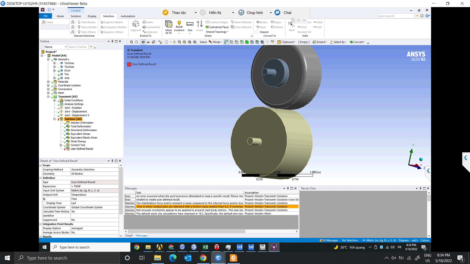
I was able to run like in this video with the first post. Since I am running the transient model, I need Command ADPL to use Type = User Defined Result, Expression=TEMP. Have you used these codes? Can you direct me to the settings? Thanks a lot.
May 17, 2022 at 7:11 pmpeteroznewman
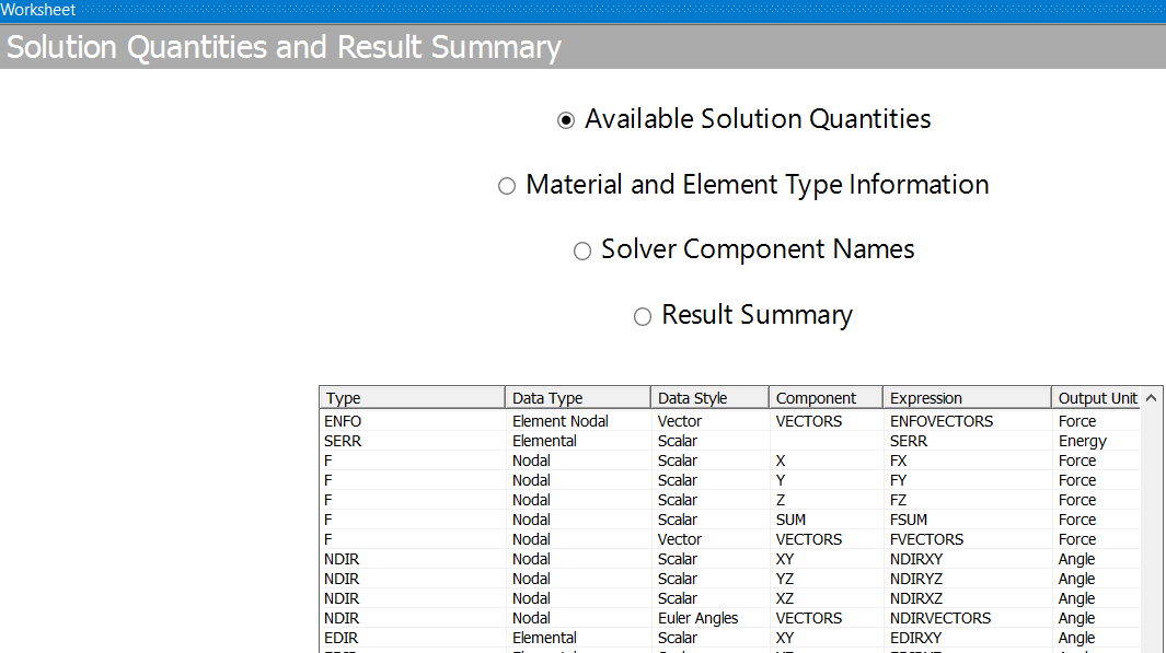
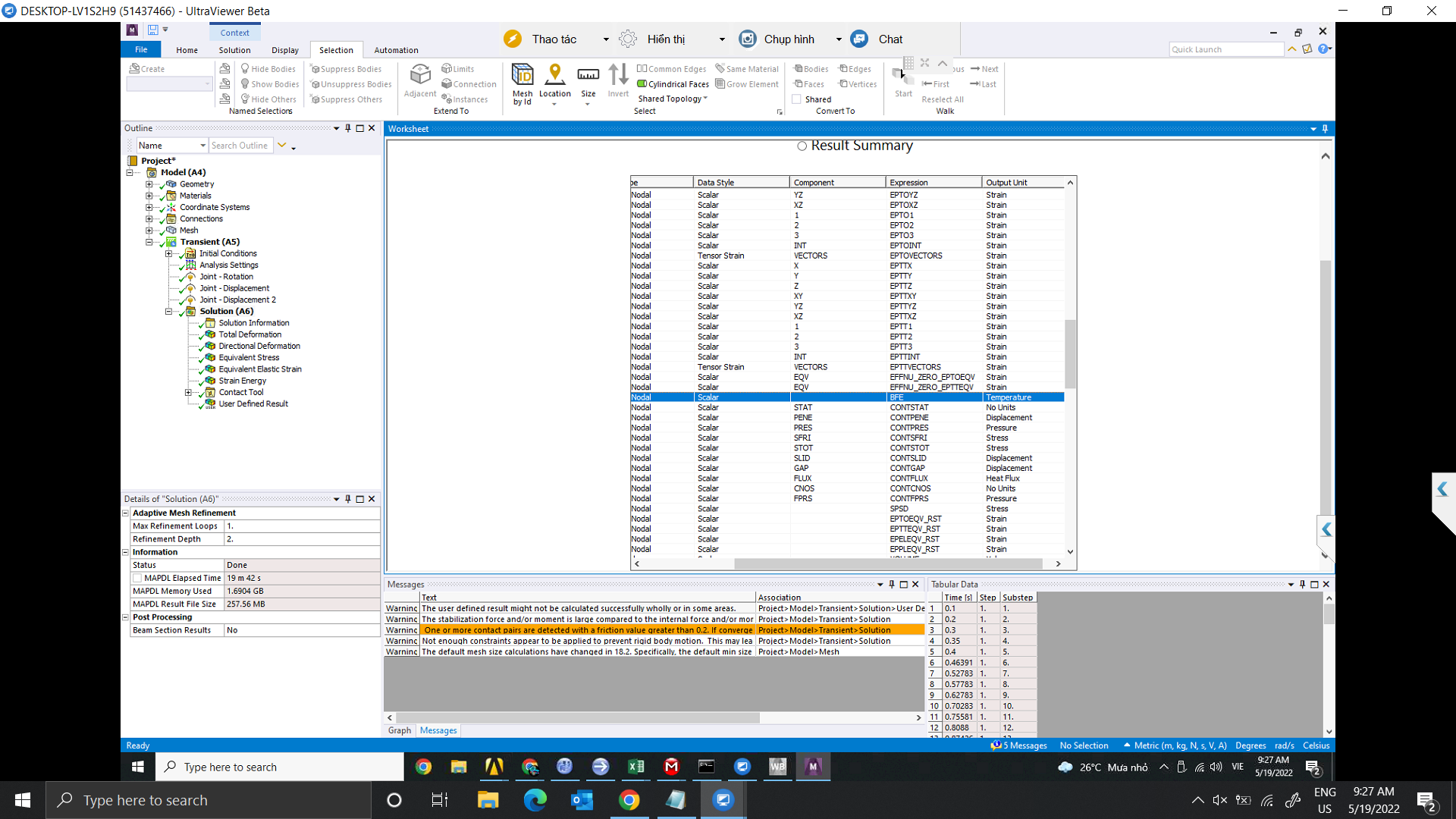
SubscriberIn Mechanical, click on the Solution branch of the Outline, then click on the Worksheet button to see the Available Result Quantities. In that table, it shows you the expression to type in a User Defined Result. Check that TEMP is in the list.
Insert a User Defined Result and type the Expression into the Details window.
/forum/discussion/29745/worksheet-result-ansys-mechanical
May 18, 2022 at 1:05 amnguyenminhhieu15122000
SubscriberThank you, Sir
I've tried it before, but the result is error.
I also tried adding this code to the Command (APDL) under the Geometry (Part/Body); Connection-Contact-Frictional; Transient Structural.
" - Part,body: et,matid,227
Connection - frictional
keyotp,cid,1,1
rmodif,cid,15,1
rmodif,cid,18,0.5
Transient structural:
tref,22
cmsel,s,temp
d,all,temp,22
allsel,all
here, temp is the named plane generated from Name Selections. 22 is the tire inlet temperature. However, while running the result still gives an error
May 18, 2022 at 11:32 amMay 18, 2022 at 1:40 pmMay 18, 2022 at 8:19 pmpeteroznewman
SubscriberIn the first image, you have Solution Information folder selected in the Outline. That is why you are not getting the worksheet I asked for.
Select Solution branch in the Outline, then on the Solution tab, click the Worksheet button on the ribbon. Then you will see the Available Solution Quantities.
May 19, 2022 at 2:31 amMay 19, 2022 at 12:24 pmpeteroznewman
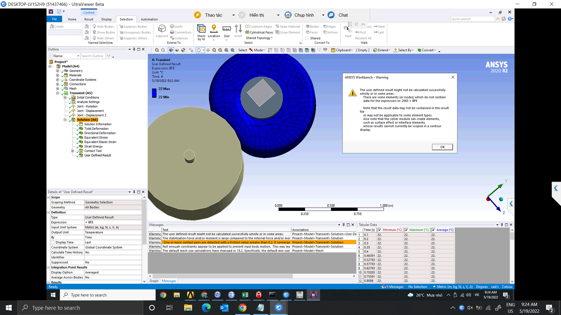
SubscriberThe BFE result plot is correct, the temperature of the elements is 22 C, your Environment temperature. What you mean is that is not what you want.
You provided three papers that have three different methods that result in a temperature distribution in the tire. Which method are you going to choose?
The second paper simply had a table of heat generation rates for different parts of the tire. That was the simplest method and you finished a model like that.
The first paper had an ABAQUS material model that generated heat as a function of deformation. Have you figured out how to do that in ANSYS? I suggested you explore that using a one element model.
The third paper relies on having two properties of rubber from a dynamic mechanical testing (DMA) machine: the storage modulus and the loss modulus. Here is more information about that: http://www.tainstruments.com/wp-content/uploads/sites/2/Introduction-to-Dynamic-Mechnical-Analysis_Akron-Workshop.pdf Do you have those properties? Have you understood how they use those properties to generate heat in the tire?
May 19, 2022 at 3:34 pmnguyenminhhieu15122000
Subscriberthank you for your support.
I think the result will be a heatsink running from a number to 22, but not 22 to 22 like in the picture
In the second paper, my results were also quite similar to their results. However, in terms of geometry, the temperature in the Sidewall is almost constant. I am not sure where is wrong, Sir
My result
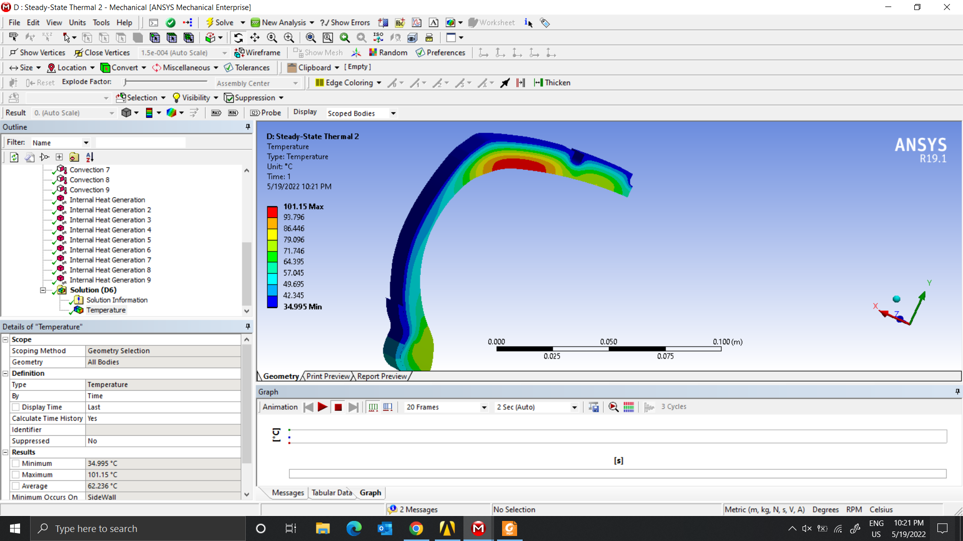 Their results
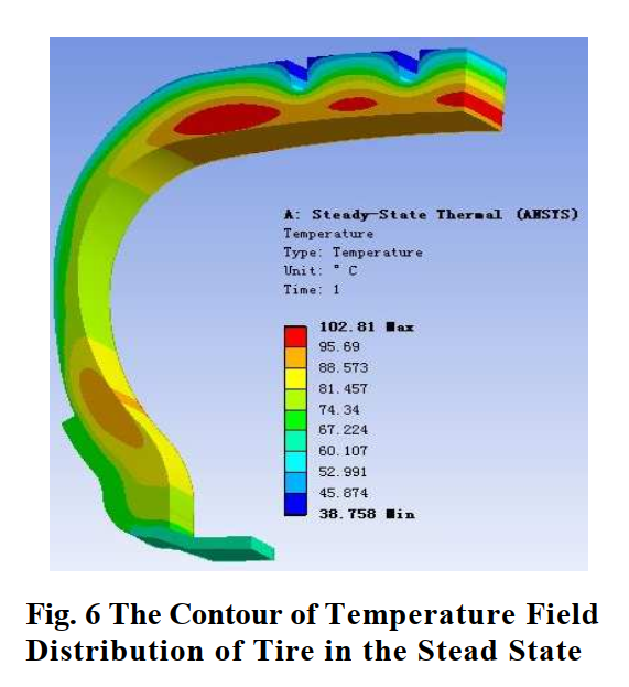
I will do 2 methods. The first is Steady-State Thermal Analysis, which is the second paper. With the Rolling Analysis method, I am confused when I don't know which paper to choose, between the Drum or Road model and how to use a one element model. I hope you can teach me more.
May 19, 2022 at 3:40 pmnguyenminhhieu15122000
Subscriberthank you for your support.
I think the result will vary from a number to 22 but not from 22 to 22.
For the 2nd paper, I'm doing it and the results can be considered almost the same. However, the temperature portion of the SideWall is almost constant.
My result
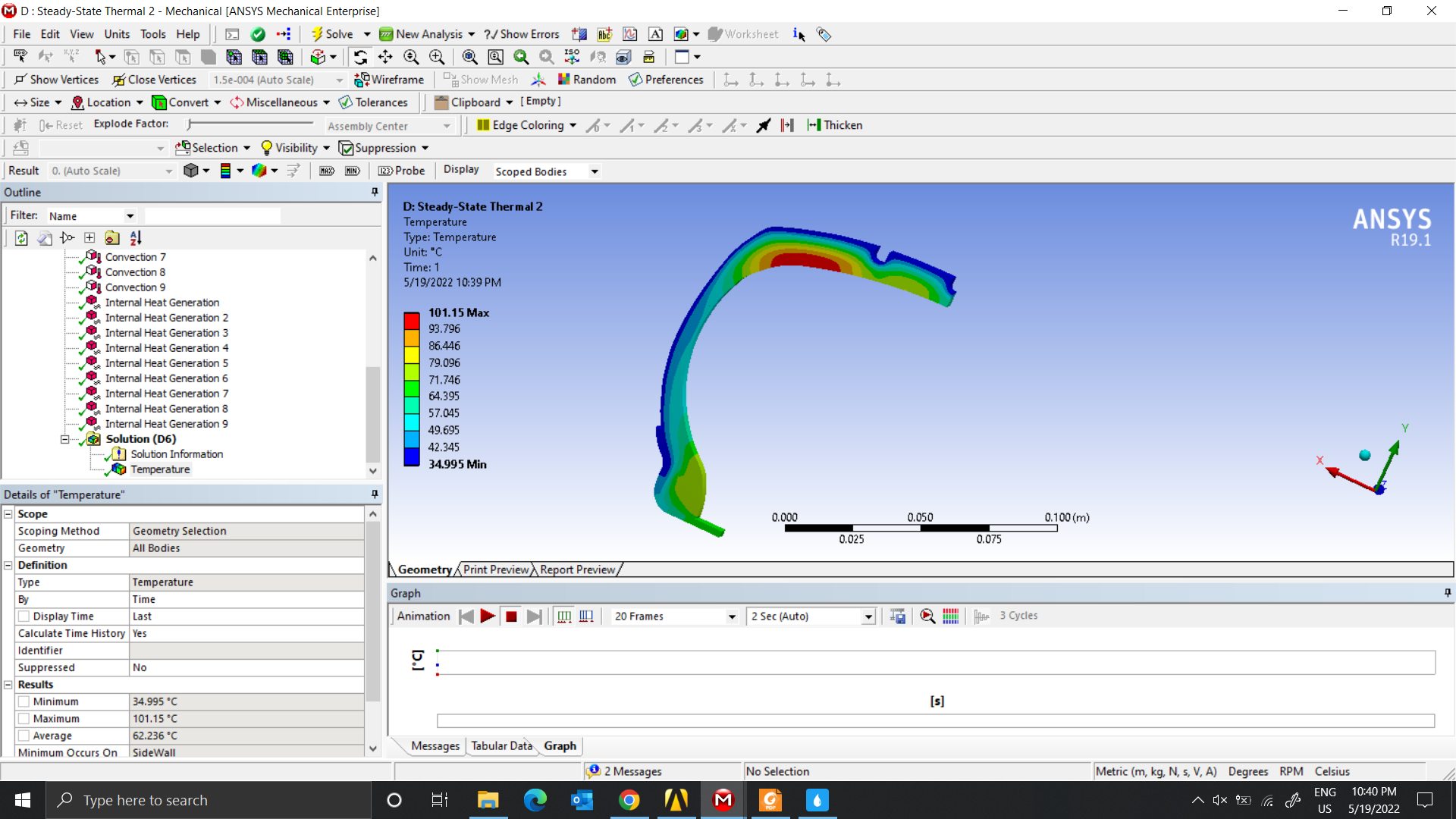 Their result
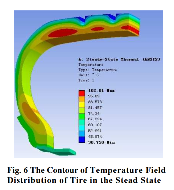 I will do 2 methods. The first is Steady-State Thermal Analysis, which is the second paper. With the Rolling Analysis method, I am confused when I don't know which Paper to choose, between the Drum or Road model and how to use a one element model. I hope you can teach me more
May 19, 2022 at 5:42 pmnguyenminhhieu15122000
SubscriberDear Sir According to the results of the second article, the greatest heat is in the Tire Tread, the heat is most focused on the Ply and Belt. However, my results show that the maximum heat is in the Liner and the maximum heat will include Ply, Belt, Liner
May 20, 2022 at 2:32 ampeteroznewman
SubscriberYou are using different geometry than is shown in Fig. 6 so you can't expect to get the same temperature distribution.
In your rolling simulation, you have not implemented a material model that generates heat during deformation so there is no reason why the temperature should change from 22 C.
Use a Drum, it is better than a Road because it can rotate as many times as you need.
The idea behind using a one element model is that it solves very fast. Rolling a tire takes a long time to solve and there is no need to wait for that time. You can find out very quickly if the material model generates heat if you use a one element model instead of a whole rolling tire model. Go back and read my description carefully and see if you can make a one element model. Then do some research on how to create a material model that generates heat caused by deformation.
May 20, 2022 at 6:24 amnguyenminhhieu15122000
SubscriberI know the model is different. However, I think the results will still be obtained for the location with the highest temperature, and in terms of value it will be difficult to match the paper.
I will re-read your instructions about a one element model
May 20, 2022 at 3:49 pmnguyenminhhieu15122000
SubscriberI tried the model with 2 grooves on the tread, and other layers on the tire. However, the maximum value result is still done in the liner part. I think it may be because the material I chose is not correct. My wish is to achieve results like the paper where the largest part of the heat will be in the tread. Hope you will give me more suggestions. Thank you very much.
May 20, 2022 at 7:16 pmpeteroznewman
SubscriberIncrease the value of Internal Heat Generation on the materials where you want a higher temperature.
Decrease the value of Convective Film Coefficient on the surfaces that are too cold.
Increase the value of Convective Film Coefficient on the surfaces that are too hot.
May 21, 2022 at 9:09 amnguyenminhhieu15122000
SubscriberThank you Sir
Do you think the Mooney - Rivlin and Thermal Conductivity coefficients need to be changed?
May 21, 2022 at 5:01 pmpeteroznewman
SubscriberWhen following the 2nd paper, Mooney-Rivlin properties aren't relevant in a Thermal model.
Increase the conductivity of materials that are too hot.
Decrease the conductivity of materials that are too cool.
Adjustments to material properties and boundary conditions untethered from any physical testing means you are adjusting the colors in the plot to make it look the way you want. It's no longer a physics simulation, it's more of an artistic creation.
-
June 23, 2022 at 1:58 am
nguyenminhhieu15122000
SubscriberHello @peternew
Can I get more help from you? Thank you so much.
May 22, 2022 at 3:18 amMay 22, 2022 at 9:43 amnguyenminhhieu15122000
SubscriberI have re-read what you pointed out on the previous pages and have a little better understanding. I don't know what model it will be created in Ansys, hope you can guide me further.
May 23, 2022 at 4:18 pmnguyenminhhieu15122000
SubscriberCan you help me again? Thank you so much
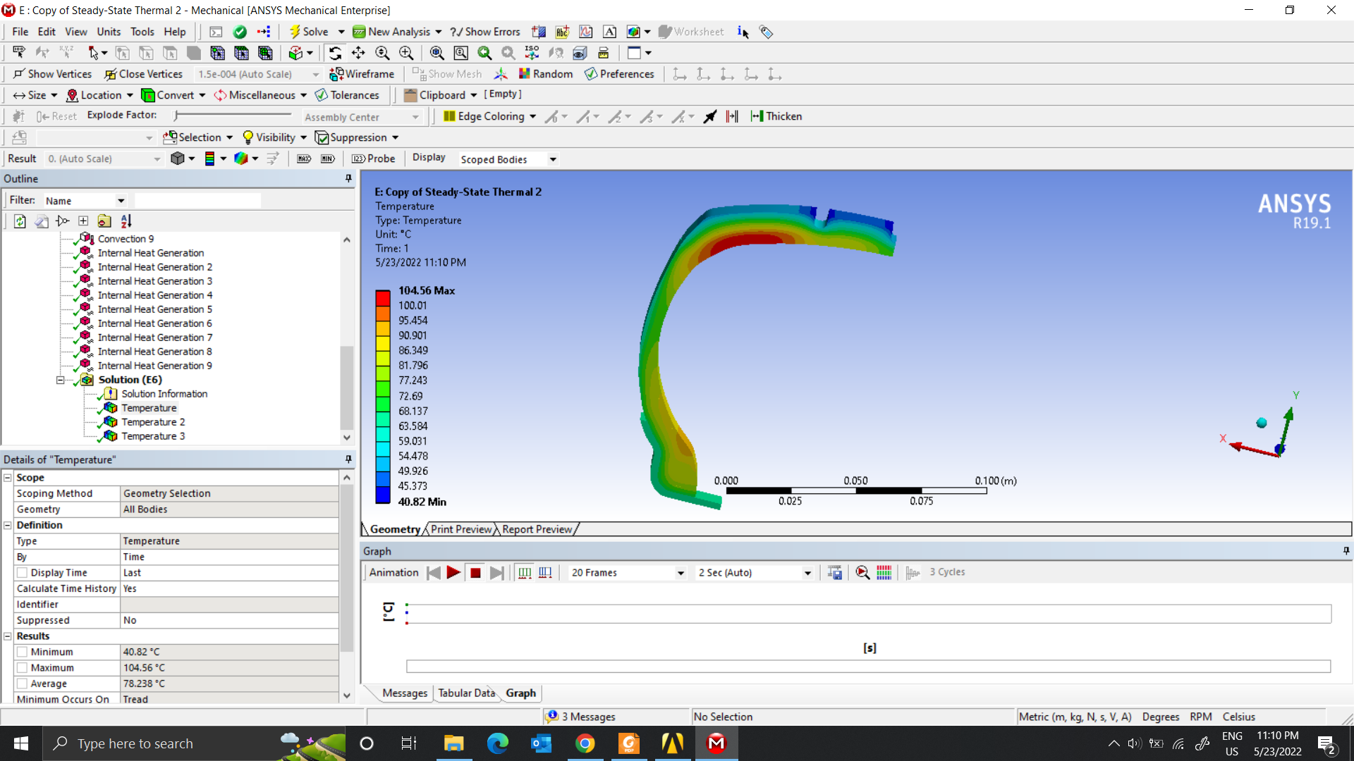
I will not change the boundary conditions that the paper refers to. I will only change the parameters of the material. However, according to the paper results, I have not yet reached the highest heat in the Tread.
I have tried with 2 models, however, the highest heat is still in the liner. I have modified the Thermal Conductivity parameter but the result is still not satisfactory.
Model 1
 Model 2
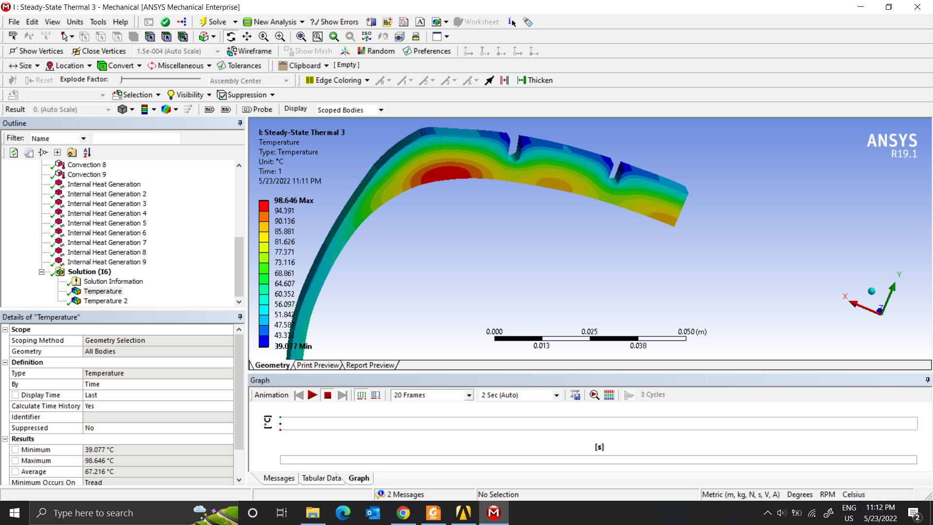 For now, I only use thermal conductivity for simulations.
Bead Wire - Rim: 60.5
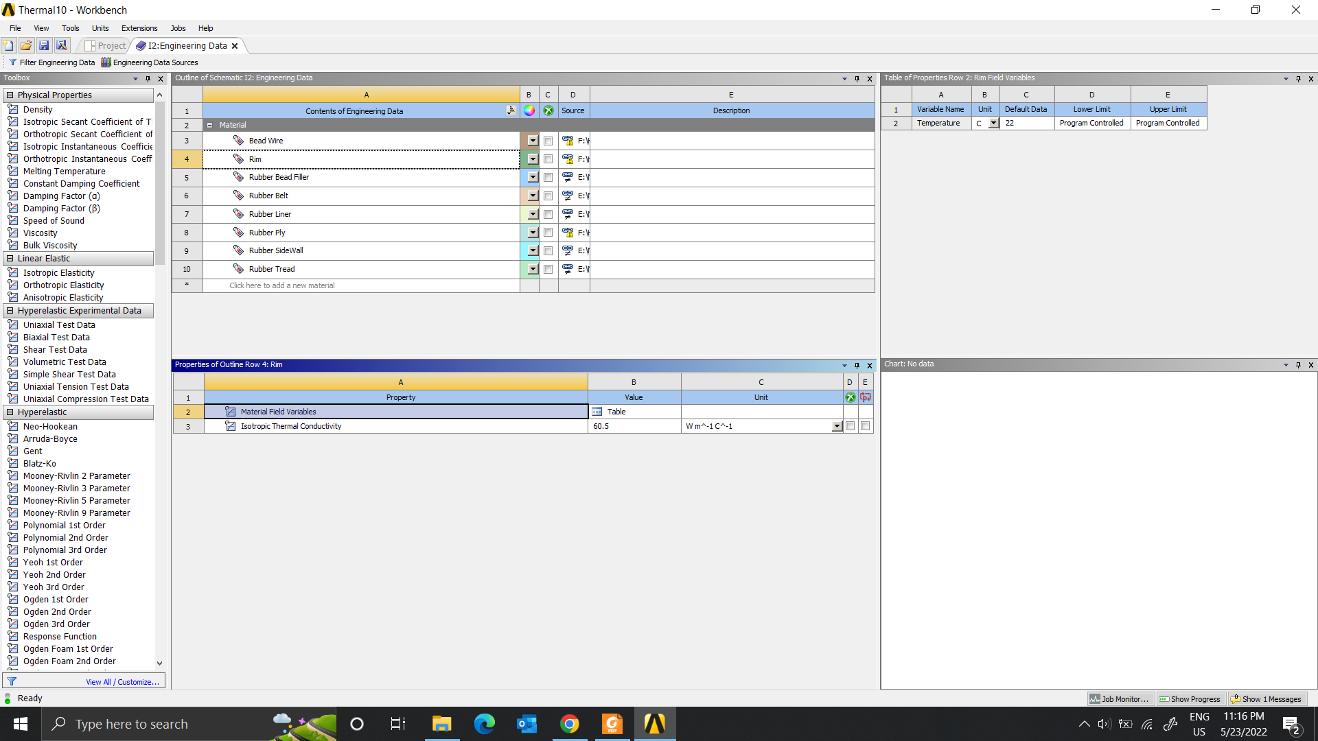 Bead Filler: 0.15
Belt 1 - Belt 2: 0.18
Liner: 0.15
Ply: 0.185
Sidewall: 0.223
Tread: 0.1625
May 26, 2022 at 10:03 amMay 26, 2022 at 10:24 amdinhan0394
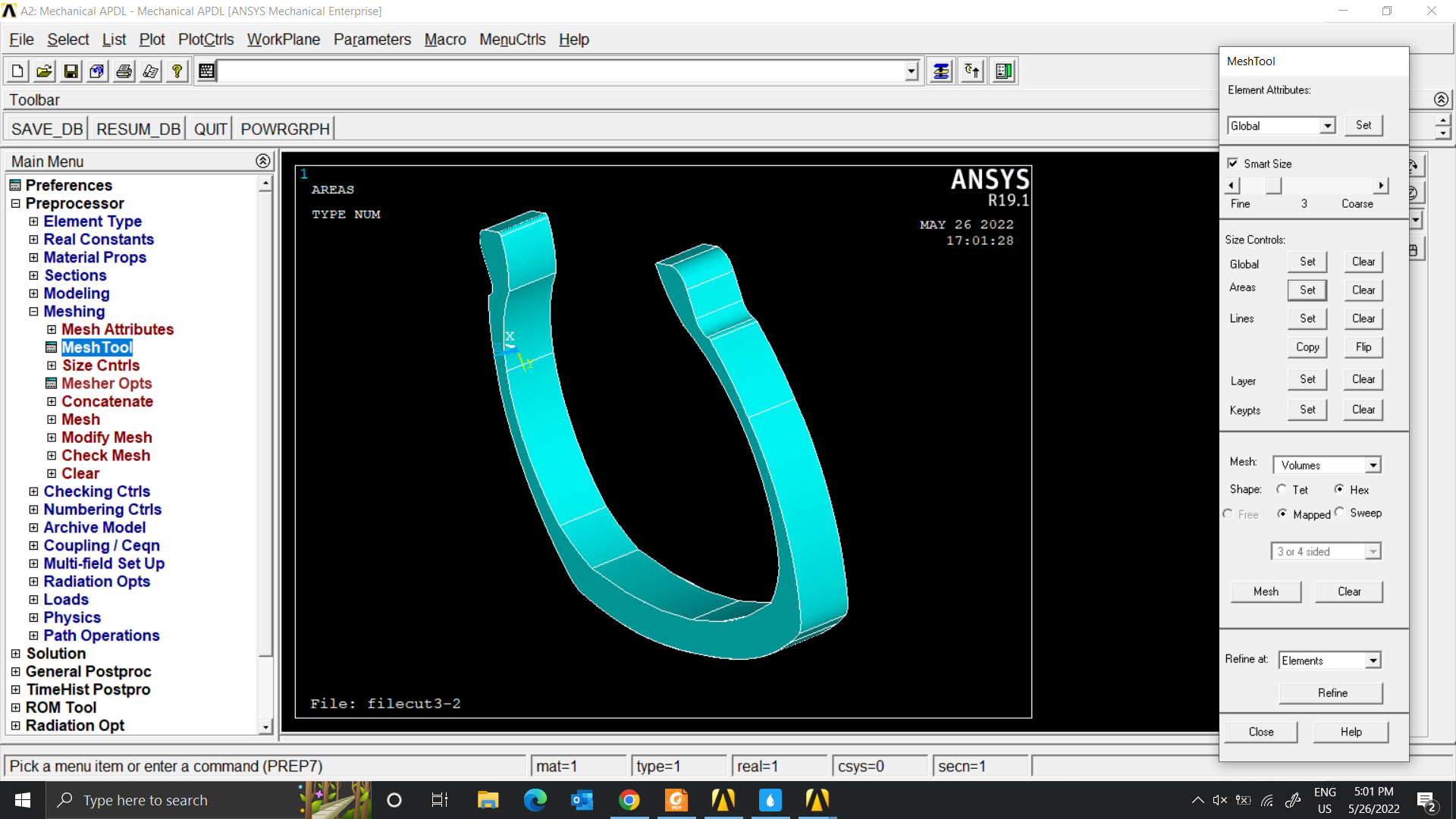
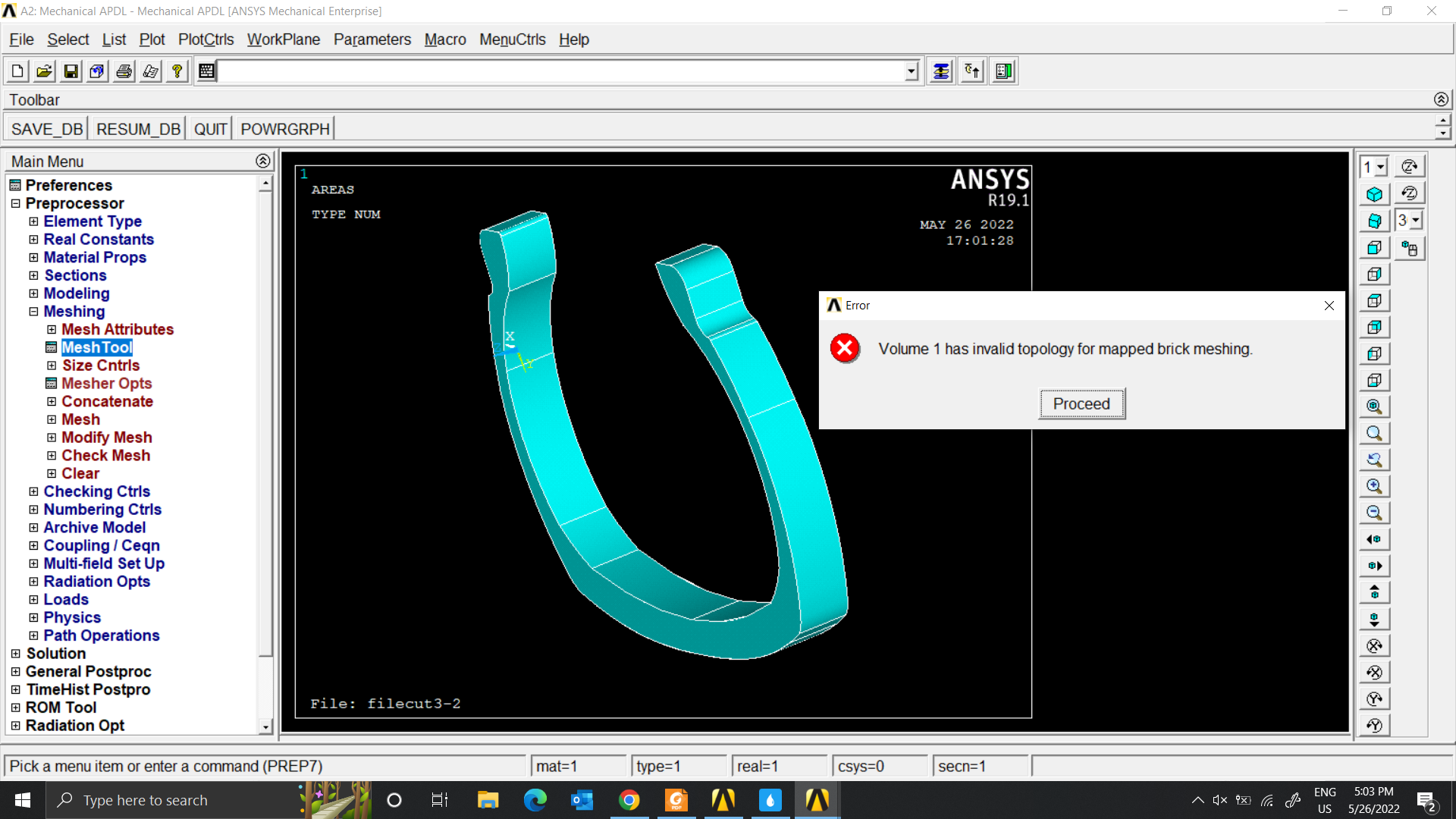
SubscriberYour model cannot mesh sweep. Please check the model again after importing whether there are hard edges/points, geometric errors,...
If you don't have much experience using APDL, you should use Workbench.
May 26, 2022 at 3:17 pmnguyenminhhieu15122000
SubscriberThank you for giving me advice.
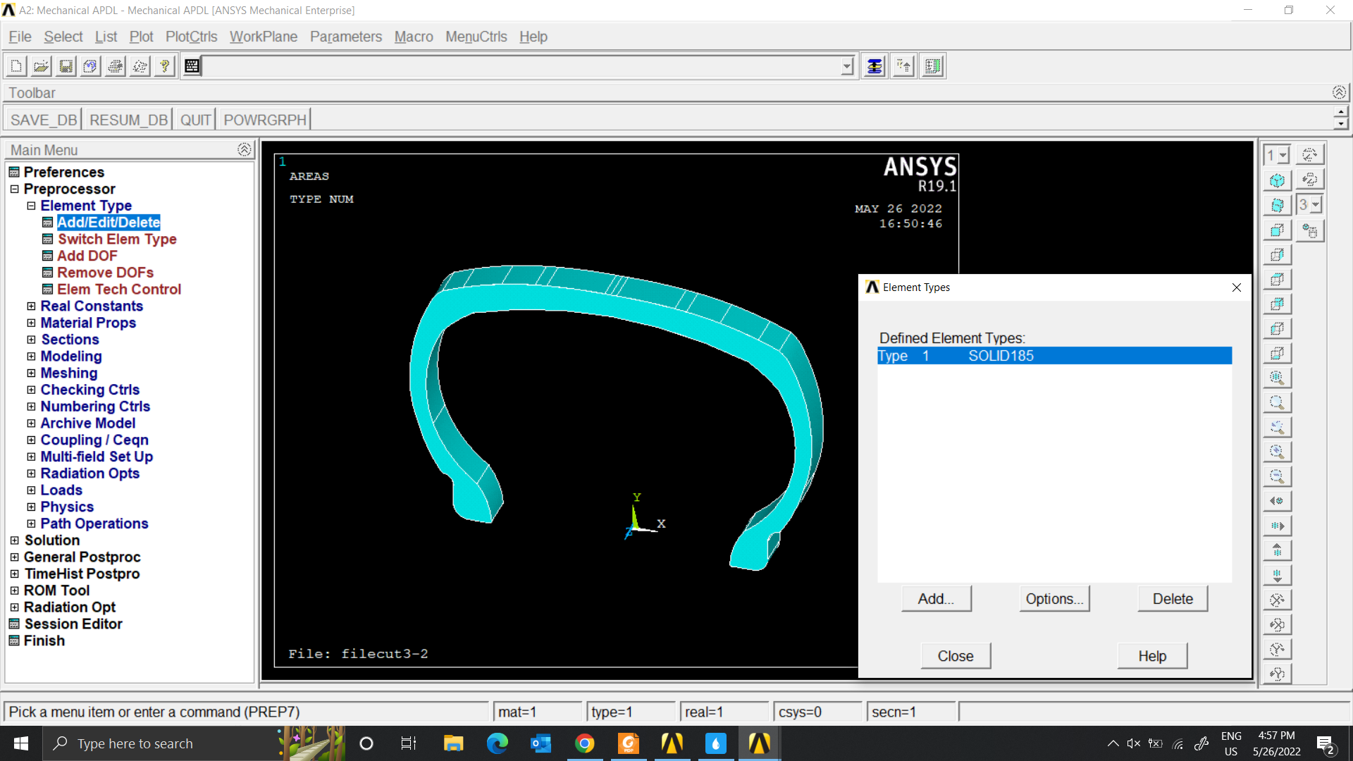
I also did modeling with Transient Structural. However, when rendering my thermal it doesn't change. I want to use more Command(ADPL) but I don't know how to use it.
I'm also new to ADPL, so it's a bit difficult to solve. Here, I want to set up the mesh type for each part like solid185 for the tire, target170 with the locked road surface and use conta174 for the connection. Then add load, pressure and speed conditions to the tire and see its temperature.
If I'm lucky, can I ask for your help? Thank you so much.
May 27, 2022 at 5:20 amdinhan0394
SubscriberI'm not recommend to use APDL.
You can post questions here or private
June 1, 2022 at 4:43 amnguyenminhhieu15122000
SubscriberCan I ask you?
I'm stuck at the heat output for the problem.
If I use the BFE function (I think it's Body Temp) then my whole model has no temperature variation.
If I use Command(ADPL) then I am selecting the road surface and the outside surface of the tire is heat generating.
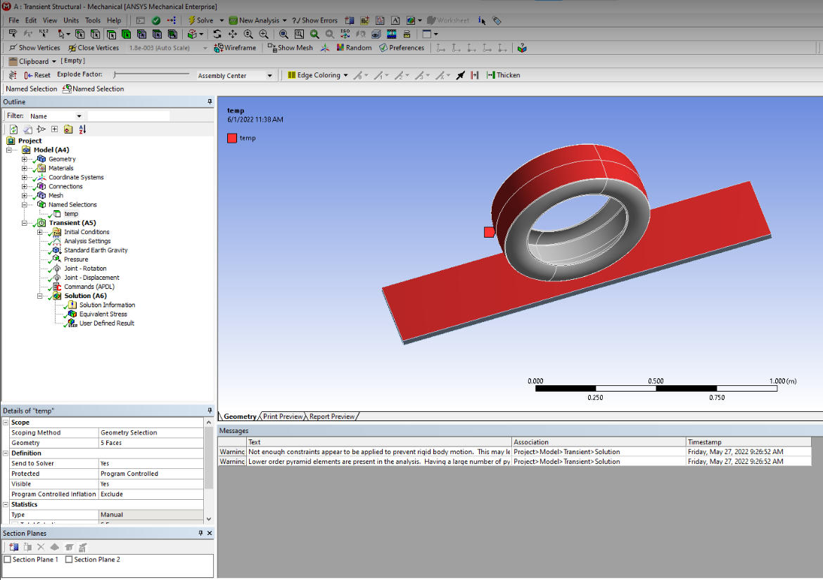 Here is the result
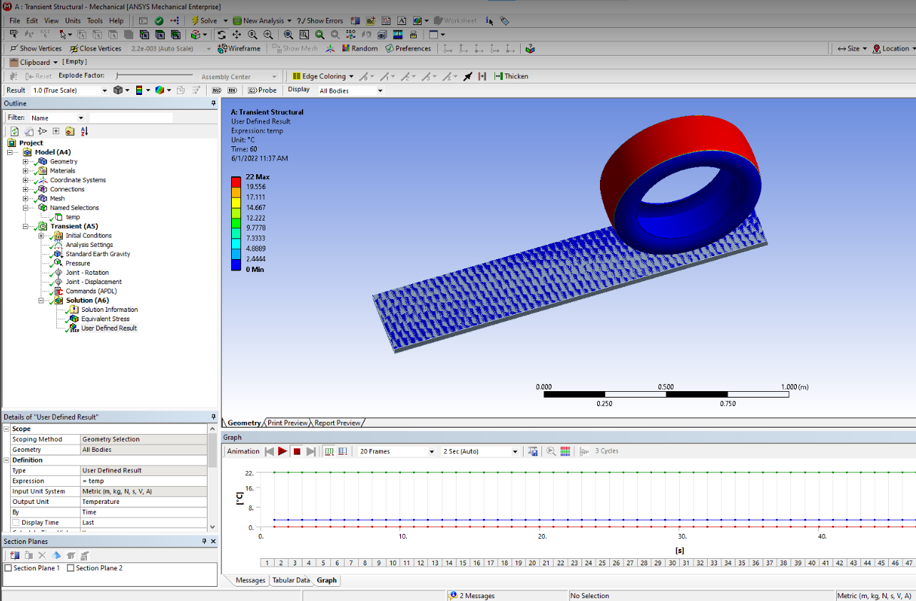 I hope you can help me.
June 1, 2022 at 6:43 amdinhan0394
Subscriberyou can send to my email ( you have contacted before, cae***)
June 1, 2022 at 7:46 amnguyenminhhieu15122000
SubscriberThank you very much
I think I know where I went wrong. I'll run back and I'll ask you again.
June 24, 2022 at 4:31 pmnguyenminhhieu15122000
SubscriberHello @peteroznewman
Can I get more help from you? Thank you so much.
Viewing 108 reply threads- The topic ‘Heating through rotating friction’ is closed to new replies.
Innovation SpaceTrending discussionsTop Contributors-
4778
-
1565
-
1386
-
1242
-
1021
Top Rated Tags© 2026 Copyright ANSYS, Inc. All rights reserved.
Ansys does not support the usage of unauthorized Ansys software. Please visit www.ansys.com to obtain an official distribution.
-


Ansys Assistant

Welcome to Ansys Assistant!
An AI-based virtual assistant for active Ansys Academic Customers. Please login using your university issued email address.
Hey there, you are quite inquisitive! You have hit your hourly question limit. Please retry after '10' minutes. For questions, please reach out to ansyslearn@ansys.com.
RETRY
