-
-
February 9, 2019 at 10:22 pm
colintho
SubscriberHello,
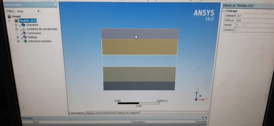
I am trying to simulate in 3D a copper pipe passing through water maintained at 3 degrees Celsius with air passing through the pipe. The air at inlet is 20 degrees and enters at 0.3m/s.Â
Â
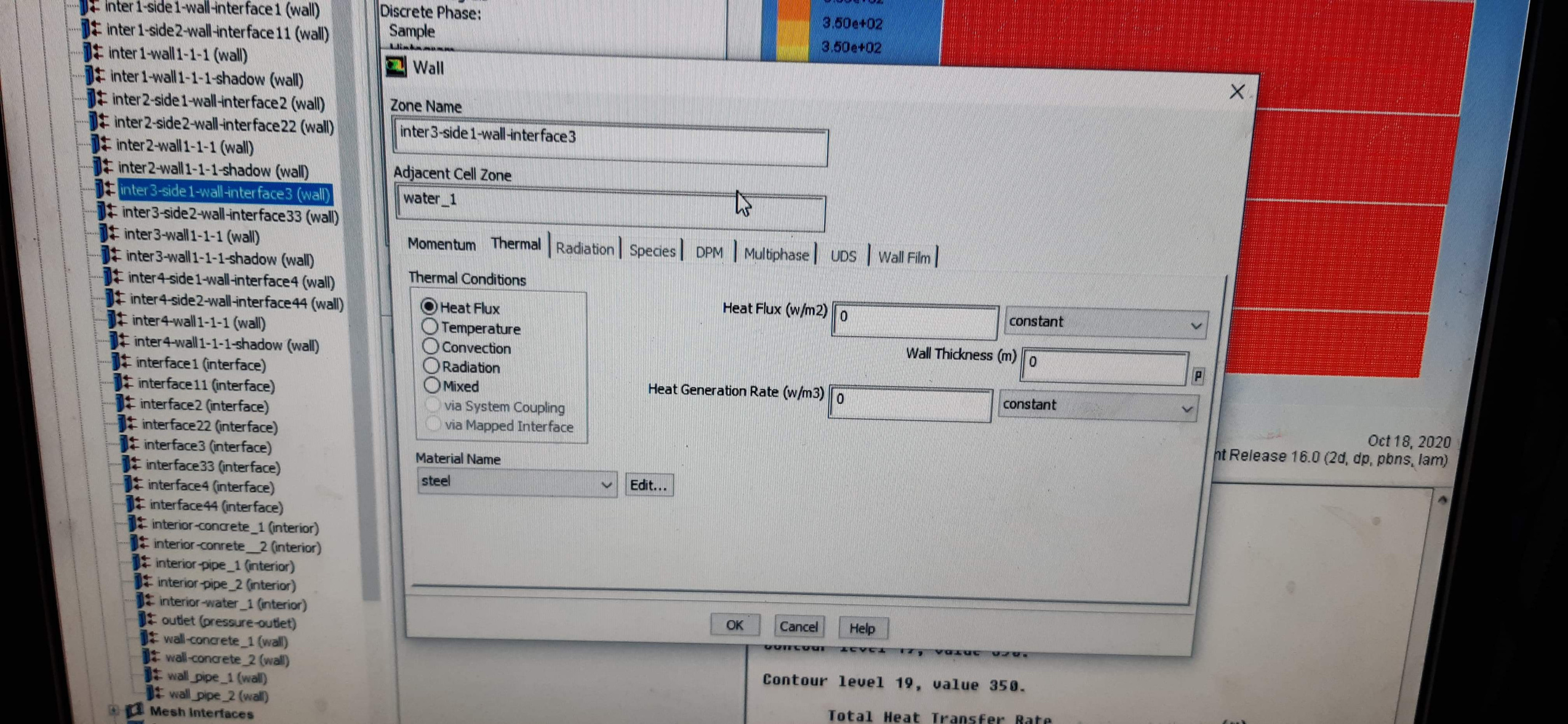
It can be assumed the pipe wall temperature is 3 degrees but when I try create this simulation the pressure outlet requires me to define a temperature when this is actually what I am trying to calculate!
Â
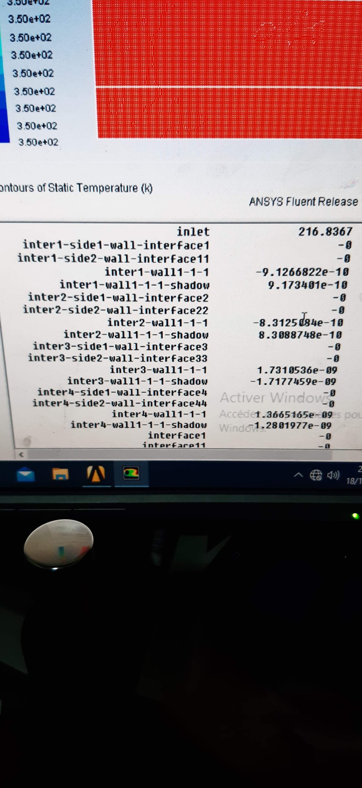
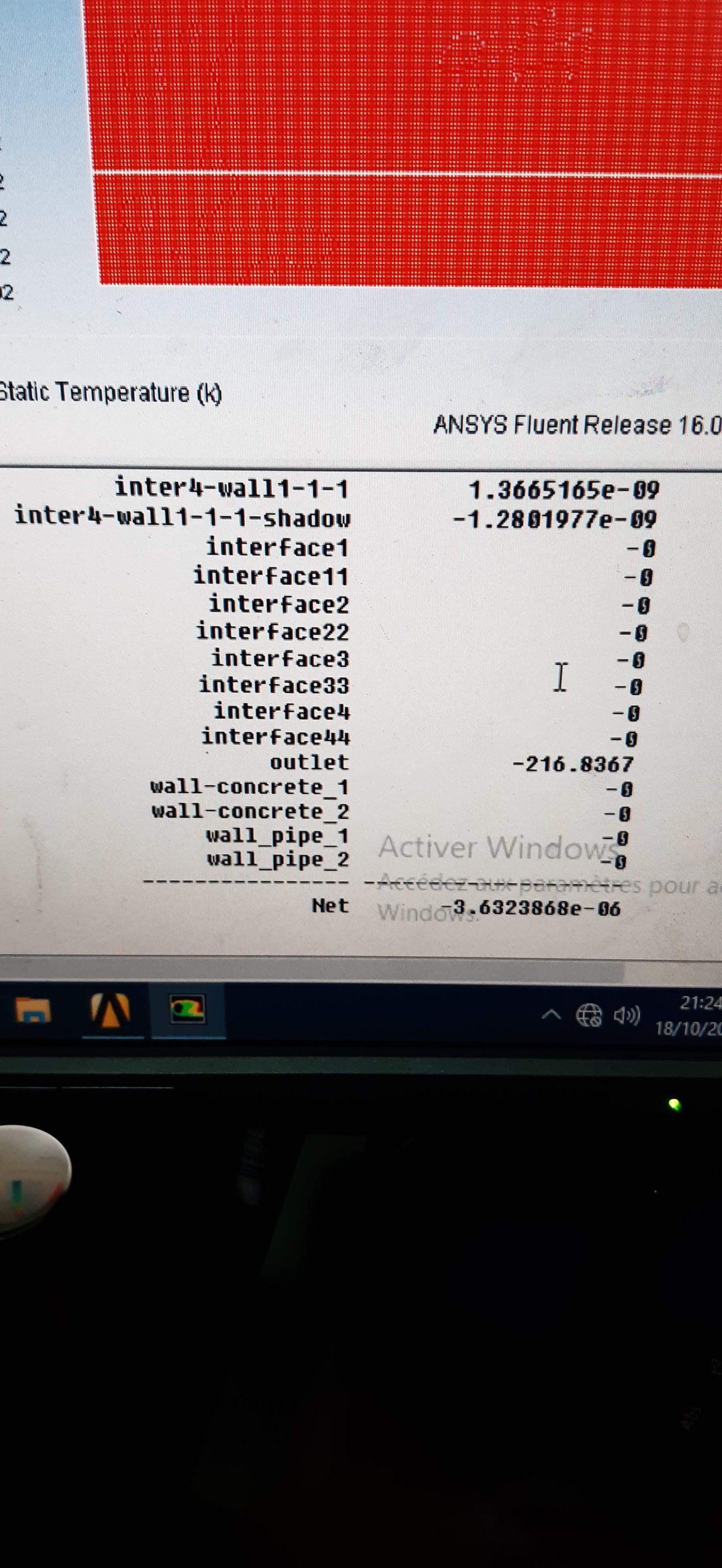
What is the best way to set this up, I have tried modeling the pipe wall with a frozen fluid volume and I have also tried to model just a soli cylinder and said the fluid to be air and assigned a wall to the outer of the volume but neither appear to work to tell me what the temperature is at the end of the pipe!
Â
Any advice would be appreciated or if there is any examples you can upload that would also be great just so I can understand how to do this simple simulation!Â
Â
Â
-
February 10, 2019 at 2:38 am
peteroznewman
Subscriber Hello Colin,
The quickest way to model this is to use an axisymmetric model. Just draw the a rectangle for the air along the X axis on the +y side to represent a radial slice.
The outlet asks what the Backflow temperature is, not what the temperature of the outflow, that will be calculated.
https://youtu.be/4iSwO4DguDw
Â
Any CFD experts with improvement suggestions are most welcome to reply with comments.
-
February 11, 2019 at 9:26 am
seeta gunti
Ansys EmployeeHere are the two tutorials on Conjugate heat transfer which give the heat transfer of fluid and solid.Â
At the outlet, you need to give the boundary condition. Fluent will ask for backflow temperature at the outlet.
Â
https://www.youtube.com/watch?v=ApLGna4oMis
https://www.youtube.com/watch?v=-03gO3UwFeA
-
February 12, 2019 at 10:32 am
colintho
SubscriberThanks for running through that tutorial Peter, I have managed to do the pipe in 2D and have since modeled it in 3D too and got it to work properly!
Also thanks Seta for those tutorials!
-
October 18, 2020 at 6:37 pm
Abdmen
Subscriberhow did you solve the problem, me too i'm struggling please some help and Thank you n -
October 19, 2020 at 12:03 am
peteroznewman
SubscribernPlease reply with a specific issue that you are struggling with.n -
October 19, 2020 at 7:27 am
Abdmen
SubscribernI want to simulate water flow inside a pipe of steel.covered with concrete, i do the simulation in 2D. I create one part, i identify the interfaces between water and betwen the other materials, when going to the fluent setup for the interface between the pipe and water the material is steel, but when runing the simulation the results are not good it temperature of water remain constant the same for all other materials. Here are some picture of my problem and thank you so muchnnn
-
October 19, 2020 at 10:52 pm
peteroznewman
SubscribernI suggest you start a New Discussion. It is confusing because your problem is different than the original poster's problem.nPlease reply with a simple hand sketch of the water, steel and concrete cross-section. Label the temperature and flow rate of the water. Label the thermal boundary condition on the Concrete. Mark the radius of the water, OD of the steel and OD of the concrete. Mark the length of the pipe.nI assume you are looking for a steady state solution.nYou should make this model as an axisymmetric model. That means the pipe centerline lies along the X axis and you draw a rectangle for the radial dimension of the water on the +Y axis. Make another rectangle for the steel, then a third rectangle for the concrete. Don't draw any rectangles on the -Y side of the X axis.nIn your replies, if you need a screen snapshot, use a screen capture program like Snipping Tool instead of using your cellphone camera.n -
October 19, 2020 at 11:01 pm
Abdmen
Subscribernits just a simple model which doesnt work, my real one is not symetric, it's composed of multiple layers, with this one which is simple i dont get good results always the energy residual starts from 10e-16. moever the interface between the pipes and concrete is generated in setup as interior i dont know why.nthank you sir for your helpnn n -
January 18, 2021 at 4:28 am
sairuthwick
SubscriberHello Peter,nnI have followed your video instructions. I have solved the 2D problem in two different Lengths. The problem solved successfully when I used a half inch pipe with a length of 2000mm. However, when i tried to solve the same problem with same mesh setting changing the length to 6000mm. There seems to be problem with meshing.nI have uploaded the screenshots. The first screenshot shows the design of 2D model without meshing. Where it looks fine.nnnAfter using the default program controlled meshing or the mesh settings suggested in your video, the design seems to transform into a different shape as shown in the below figure. n
nis this issue caused due to the poor meshing ?.Thank you in advance.n
-
March 22, 2023 at 10:12 am
Fahad m
Subscriberis it possible to simulate a HX without using CFD? convection coe. values are already calculated
-
March 22, 2023 at 12:02 pm
peteroznewman
SubscriberIn Workbench, select a Steady State Thermal analysis or a Transient Thermal analysis and use a Convection boundary condition where you can type in the convection (film) coefficient.
-
- The topic ‘Heat transfer through pipe wall’ is closed to new replies.
-
3487
-
1057
-
1051
-
955
-
922
© 2025 Copyright ANSYS, Inc. All rights reserved.