-
-
January 26, 2024 at 2:42 pm
Jose Amigo
SubscriberHello everyone,
I was having trouble in defining a heat source for an electric heater. I've isolated my heater completly from the rest the domain to understand it bettter.
It's 2D transient conduction problem + heat source term in a rectangle. All the walls are adiabatic. The heat source is 500W, and the volume of the domain is 0.0002 m3, so I've defined the volumetric heat source to be 2500000 W/m3.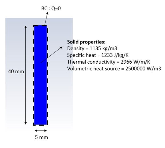
I would have expected the average temperature evolution would follow this equation: *Cp*Volume*dT/dt = Qin
However, the average temperature evolution is extremely slow and doesn't follow the previous equation. It only follows that eq. if I force the thermal conductivity of the material to be close to zero.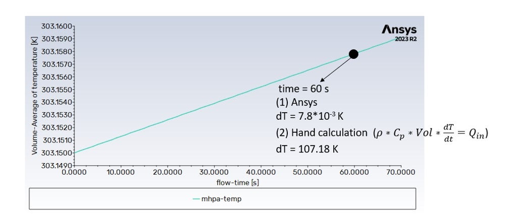
Why would the average temperature evolution be sensible to thermal conductivity if the heat source is the same and has adiabatic boundaries?
Any help is fully appreciated. -
January 30, 2024 at 11:34 am
Jose Amigo
SubscriberHi, just adding some comments to complement my previous post.
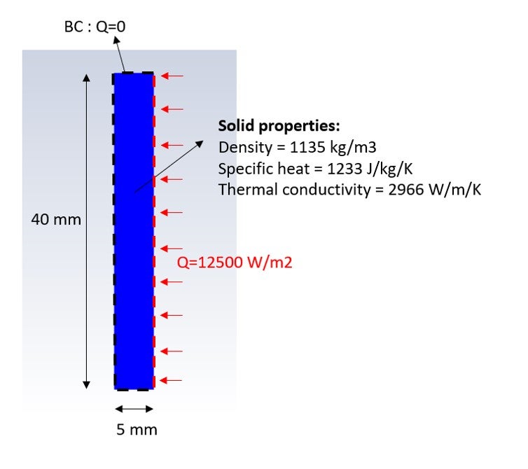
If I try to add the same 500 W on the right boundary, instead of having them through a volumetric heat source, I also get a very small heating rate.
I understand Fluent is doing the following on the right boundary:
Qheat = K*dT/dx [W/m2]
Since the thermal conductivity of my material is high, the change in temperature ends up being very small. However, is there a way to make this heat input (Qheat) consistent with the first equation I posted? This is, the transient evolution of the average temperature of the solid, which is not dependent on the thermal conductivity:
rho*Cp*Vol*dT/dt = Qheat [W]
Thanks!
-
February 7, 2024 at 11:00 am
Essence
Ansys EmployeeHello,
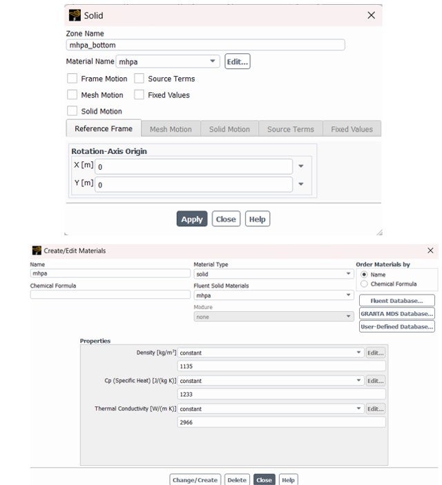
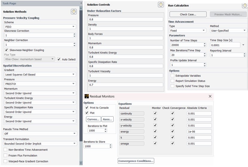
Could you share the screenshots of the temperature contours? Also please show the mesh and the case setup panels.
-
February 8, 2024 at 2:17 pm
Jose Amigo
SubscriberHi, thanks for the reply!
I'm adding 3 pictures:
- Mesh
- Setup
- Temperature contour
I realized that decreasing the time step improves the results. However, I have to go to very small time steps (< 10^-6 s) to start having a similar result than the analytical solution. Considering this is a basic problem, is it normal to require such a small time step when it comes to materials with high thermal conductivity? Or am I doing something else wrong?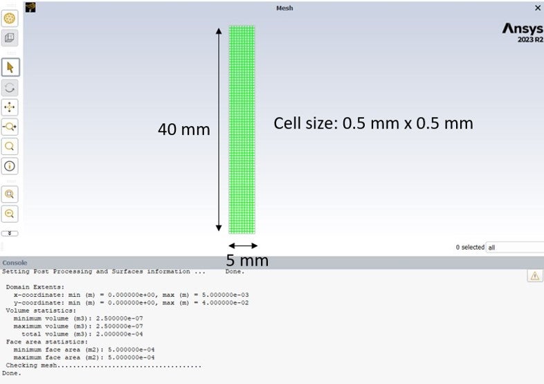
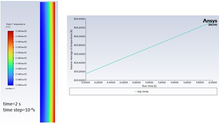
Note: from the analytical solution, after 2 seconds the temperature should have been around 304.9K, but the time step here (10^-4 s) was not small enough. -
February 8, 2024 at 2:32 pm
Essence
Ansys EmployeeThanks for the screenshots. Could you also show the materials just to be sure?
-
February 8, 2024 at 3:05 pm
-
February 9, 2024 at 8:25 am
Essence
Ansys EmployeeCould you try using the URFs equal to one, please?
-
February 9, 2024 at 9:42 am
Jose Amigo
SubscriberGreat, this helped. By changing all URFs to one I was able to get a good result with 0.01 s time step already (instead of 10^-6 s).
Thanks!
-
- The topic ‘Heat source in 2d solid’ is closed to new replies.


-
4683
-
1565
-
1386
-
1242
-
1021

© 2025 Copyright ANSYS, Inc. All rights reserved.

