-
-
April 22, 2022 at 8:49 pm
inouzil
SubscriberHi,
I am conducting a thermal analysis in fluent. The deformed geometry from a machining simulation is brought into Fluent and the final temperature distribution with coolant is aimed to be calculated. I am facing an issue with the temperature distribution. The boundary conditions are shown in the image below. At these locations I am applying a heat flux boundary condition such that I get a total heat generation of 500W at location B and 250W from location A. This is calculated from the cutting forces.
April 25, 2022 at 4:02 pmRob
Forum ModeratorCheck the cell resolution. Do A & B correspond to a wall & wall:shadow pair?
May 9, 2022 at 6:07 pminouzil
SubscriberHi Rob Sorry, about the late response. I did not get any notification and hence was not aware.
Yes, both A&B correspond to wall &wall-shadow pair. I divide and assign the total heat flux value equally between the wall and wall-shadow. Still there is a discontinuity.
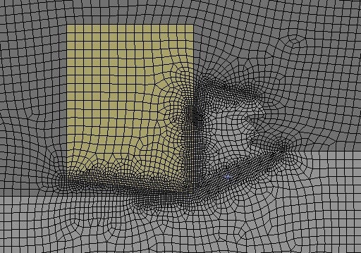
Attached below is the mesh. The element size at the walls A & B is 4e-6m. I have attached the image below.
 I replaced the heat flux boundary condition with temperature condition and then there was no discontinuity. The discontinuity exists only when I use the heat flux boundary condition and I have to use the heat flux boundary condition.
Kindly assist. Looking forward to your response.
Ibrahim Nouzil
May 10, 2022 at 11:16 amRob
Forum ModeratorDid you leave the wall & wall:shadow as "coupled" ? If you changed that you've disconnected the two parts. To add heat in and retain coupled you need to give the wall a finite (but small) thickness and add heat in as a "generation rate": the volume is wall area (one of wall & shadow, not both) multiplied by the thickness.
May 10, 2022 at 10:36 pminouzil
SubscriberHi Rob,
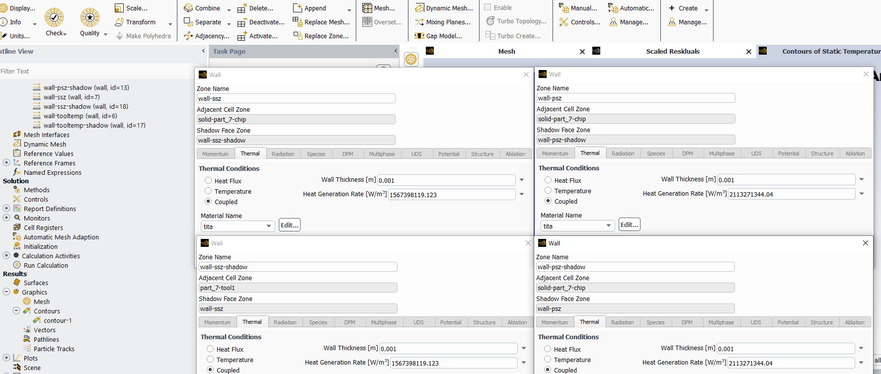
The wall is setup as coupled and heat generation rate is assigned to the walls as described. The wall setup is as shown below:
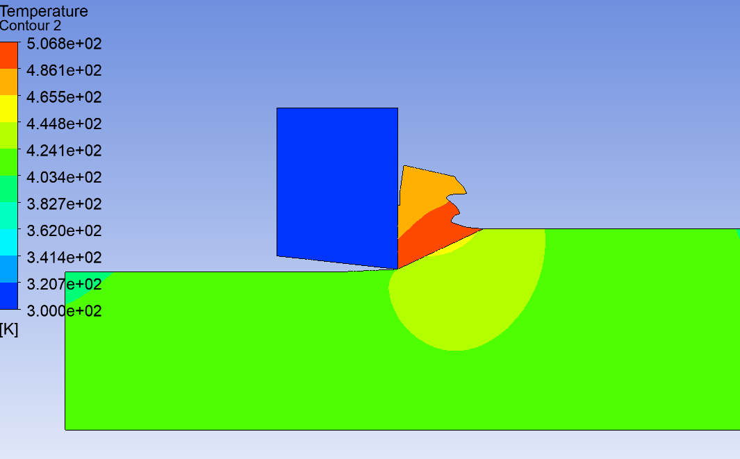
 There is still discontinuity in the temperature at the wall (result below). I have also tried it as uncoupled with similar results. The only difference is, when I run the simulation with heat flux boundary condition (uncoupled), I get higher temperatures whereas when I use heat generation rates (coupled), I get lower temperatures. However, when I check the heat flux reports at the wall, it is the same.
 The heat generation rate is calculated from cutting forces. So at wall A (Wall-SSZ) net heat transfer rate needs to be 250W and is calculated accordingly. Similarly for wall B (Wall-PSZ), heat heat transfer rate needs to be 500W. Kindly assist in understanding this issue.
Your support is much appreciated.
Ibrahim Nouzil
May 11, 2022 at 9:20 amRob
Forum ModeratorIf you find the area of the wall, thickness and generation rate how does the flux tie up with the uncoupled case? What's the near wall mesh & flow like? The latter could mean you're adding heat but the flow/mesh mean it's not getting into the fluid. Not sure what's going on in the "blue" zone, but what are the other boundaries on that zone, and what material is it?
Viewing 5 reply threads- The topic ‘Heat flow at wall in Fluent’ is closed to new replies.
Innovation SpaceTrending discussionsTop Contributors-
4718
-
1565
-
1386
-
1242
-
1021
Top Rated Tags© 2026 Copyright ANSYS, Inc. All rights reserved.
Ansys does not support the usage of unauthorized Ansys software. Please visit www.ansys.com to obtain an official distribution.
-
The Ansys Learning Forum is a public forum. You are prohibited from providing (i) information that is confidential to You, your employer, or any third party, (ii) Personal Data or individually identifiable health information, (iii) any information that is U.S. Government Classified, Controlled Unclassified Information, International Traffic in Arms Regulators (ITAR) or Export Administration Regulators (EAR) controlled or otherwise have been determined by the United States Government or by a foreign government to require protection against unauthorized disclosure for reasons of national security, or (iv) topics or information restricted by the People's Republic of China data protection and privacy laws.


