Hi, all
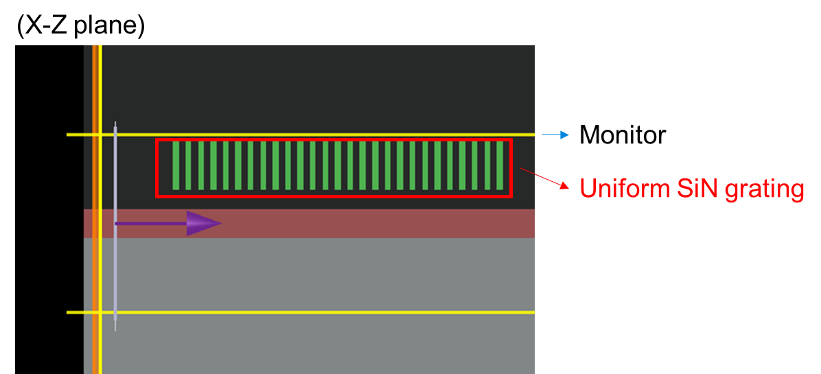
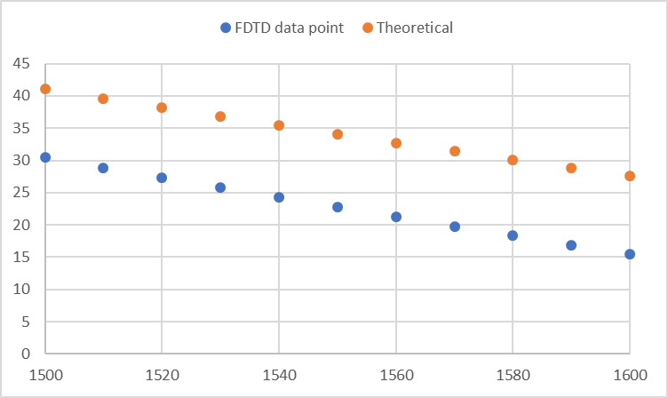
I simulated the antenna emission angle by positioning the monitor to capture the calculated far-field data, and I verified the simulation results using theoretical formulas.
The emission angle is defined as the coordinates of the maximum E^2 intensity in the far-field pattern.
The theoretical formula is given by sin(θ) = (neff * λ) / Λ, where θ represents the emission angle, λ is the wavelength, and Λ stands for the grating pitch. Following this, θ will be recalculated using Snell's law because the grating is located in the cladding.
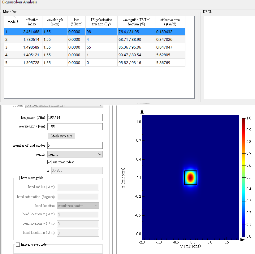
The neff value is calculated using Lumerical MODE solver under two conditions:
(1) Only Si waveguide --> neff1=2.451
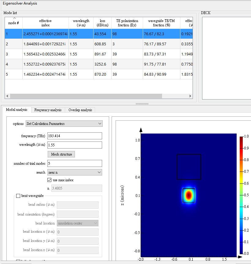
(2) SiN block and Si waveguide --> neff2 = 2.455
The simulated results were in agreement with the theoretical formulas, particularly for normal emission (θ = 0), under the conditions of SiN pitch at approximately 630 nm and a duty ratio of approximately 0.55.
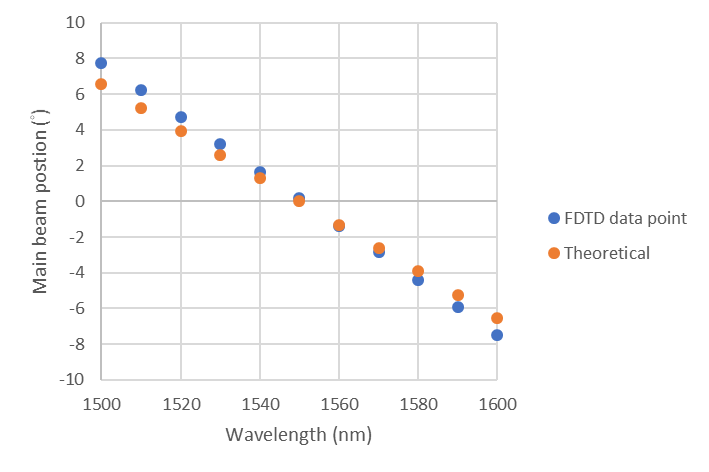
However, when I changed the SiN pitch to 750 nm (with a duty ratio of approximately 0.467), the emission angles calculated from the far-field results did not align with the values predicted by the theoretical formulas.
Please help me analyze this issue further.
Thank you.


