-
-
July 13, 2024 at 7:37 am
Sanjay Vishwakarma
SubscriberWhile performing a fracture analysis using the corner crack with Smart crack growth, I got the following warning and errors, respectively.
Warning: Fracture parameter calculation issue: crack tip node is attached to element type that is not supported, Crack 1, crack tip node 6788968, element type 174. Element will be ignored.
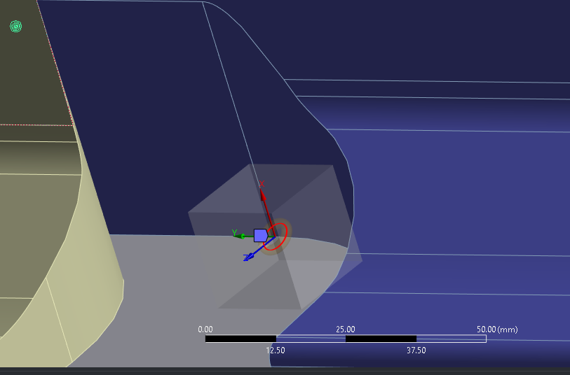
The green dot shown in the attached picture is the node number 6788968.
Error: SMART re-meshing zone contains unsupported elements (element type 170).
Please help me on this
Thanks
-
July 25, 2024 at 11:45 am
Ashish Khemka
Forum ModeratorHello,
Please see if the following forum thread helps you:
https://innovationspace.ansys.com/forum/forums/topic/the-fracture-parameters-computed-during-solution-may-be-incorrect-2/
Regards,
Ashish Khemka
-
July 26, 2024 at 1:58 pm
Sanjay Vishwakarma
Subscriber
-
-
July 30, 2024 at 2:32 pm
David Weed
Ansys EmployeeHi Sanjay,
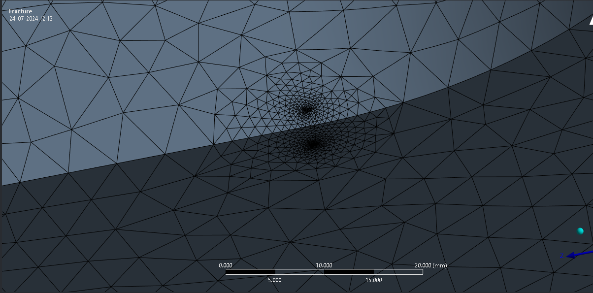
The the way that the contact pairs and fracture zone are situated are still not very clear to me but, in general, the contact area should not overlap at all with the fracture zone. This is because contact elements will negatively affect the fracture calculations. From the second picture in your last comment, it appears that the error has been resolved and now you are only receiving a warning about checking the fracture parameter calculations. If this is the case, and the fracture zone is free of contact elements, then just make sure that contours 3-6 for any fracture results are relatively close/don't diverge.
-
July 31, 2024 at 7:14 am
Sanjay Vishwakarma
SubscriberThanks for your reply Sir,
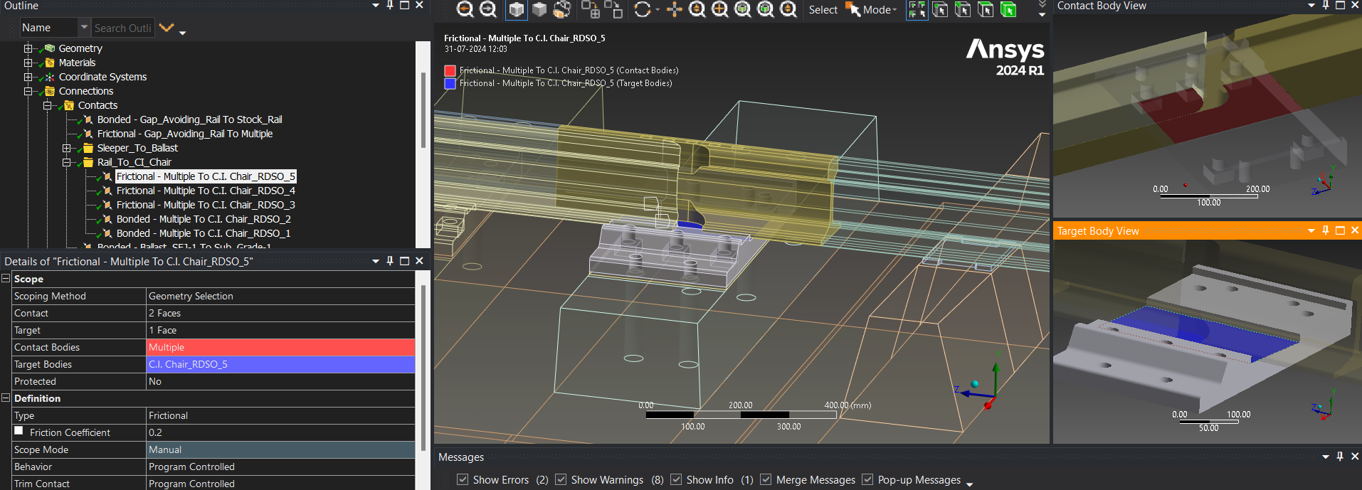
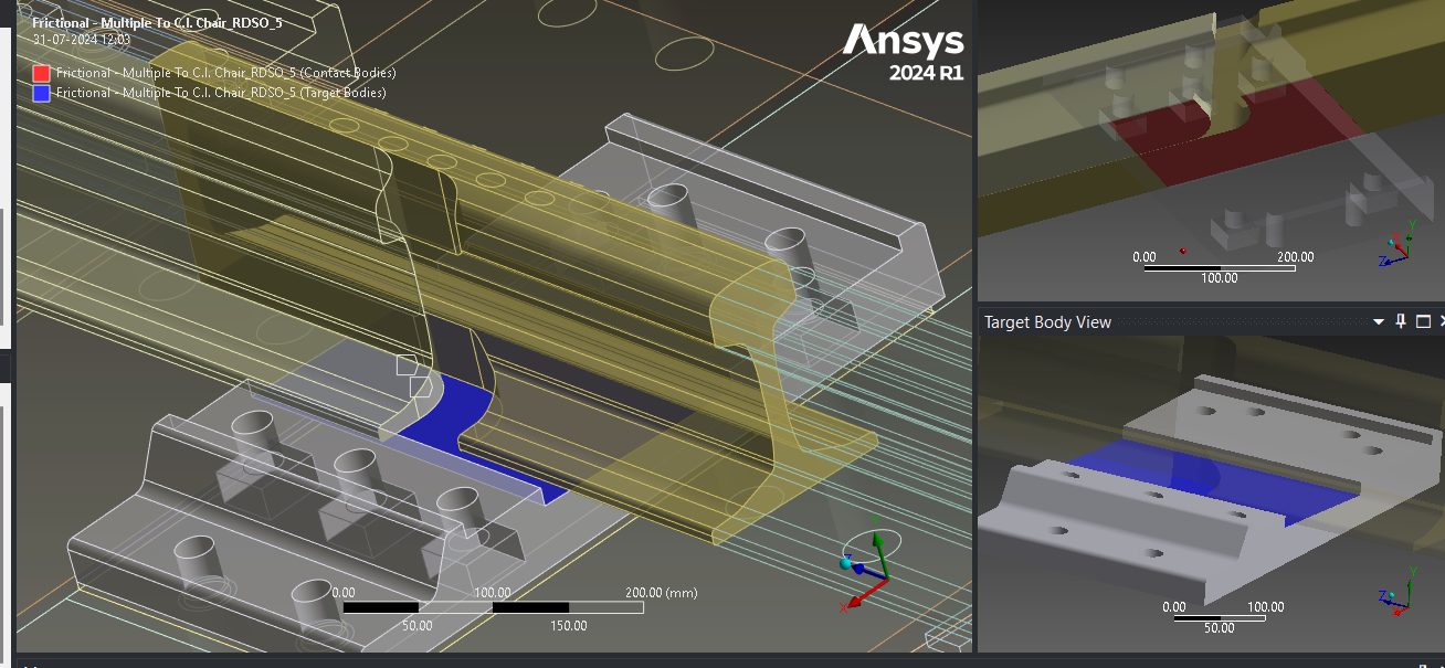
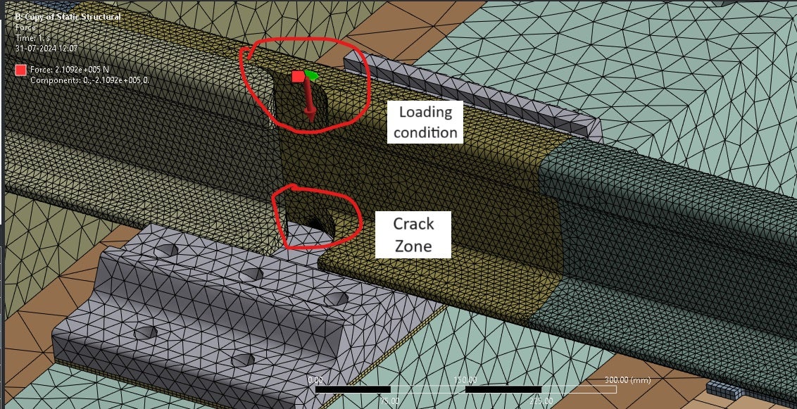
I have attached more pictures of the contact pairs and the fracture zone. As u discussed that the contact area should not overlap at all with the fracture zone but in my problem the crack is at the contact zone (under the crack zone body there is another body witch is in the frictional contact as shown in the figure).
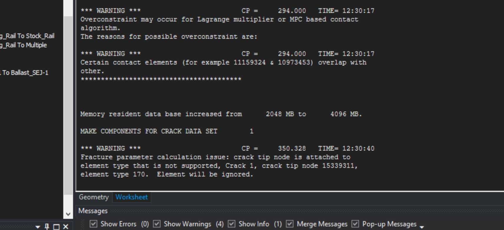
The error was still comming it is not solved. i have attached the picture from the solution information where first the warining comes after that error come.
how to resolve this problem, please help me this.
-
-
August 1, 2024 at 4:11 am
David Weed
Ansys EmployeeHi Sanjay,
For fracture mechanics simulations, contact elements are not allowed in the crack mesh region as your screenshots show. As an approximation to the sliding behavior that you want between those two surfaces, you can consider splitting the faces in order to partition the contact pairs so that they are outside of the scope of the crack mesh region but also cover enough of the surfaces to allow sliding.
-
August 5, 2024 at 12:46 pm
Sanjay Vishwakarma
SubscriberThanks for your reply, Sir
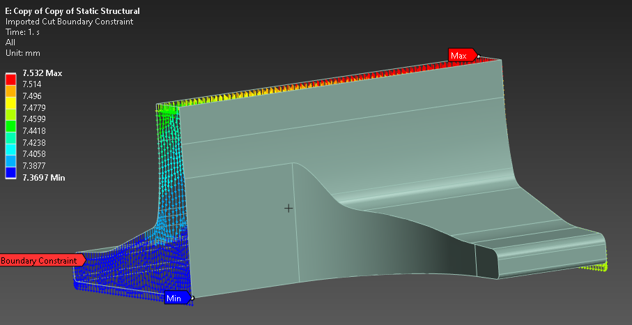
As you told me, contact elements are not allowed in the crack mesh region, so can I use the submodeling analysis technique? I tried that technique and cut a portion of the fracture zone. And perform the analysis (I have attached a picture of the cut portion).
Here, I used the cut boundary constraints conditions for the sub-modeling. But now I am getting the two problems
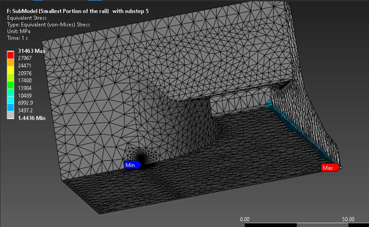
1) Getting very high stresses, which is out of range
2) The fracture problem is solved only in the single substeps. As I increase the sub-steps, it gives the error.
Please help me with this.
-
-
- The topic ‘Getting the error while performing a fracture analysis’ is closed to new replies.


-
4678
-
1565
-
1386
-
1242
-
1021

© 2025 Copyright ANSYS, Inc. All rights reserved.


