-
-
March 28, 2024 at 11:32 am
Maciej Wojdowski
SubscriberGood morning, I am in desperate need of help! I am trying to model the compression of a geopolimer sample. The only values I obtained from the laboratory are:
- Young's Modulus
- Poisson's Ratio
- Stress-strain curve (visible in the image)
Unfortunately, the geopolimer sample behaves more like cement than concrete, so I don't know which material to use from the library. What I have done is visible in the picture.
I know what force was applied during the test, but when I apply it to my model (which also includes imperfections in the form of surface roughness to which I apply the load to model shearing correctly), the stress and strain are completely different from those in the test. Please help, what am I doing wrong? Should I choose a different material model? Or are the boundary conditions and simulation settings incorrect? I attach all the necessary photos.
Please also note that the material is very brittle, practically no plastic deformation occurs. (visible on the stress-strain curve)
Material model:
Stress - Strain curve from the lab: (green one)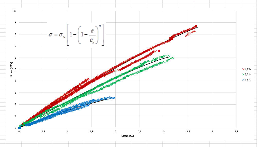
Ansys static structural model:
I applied 1kN per second until reaching 18,5kN which was the force that broke the sample.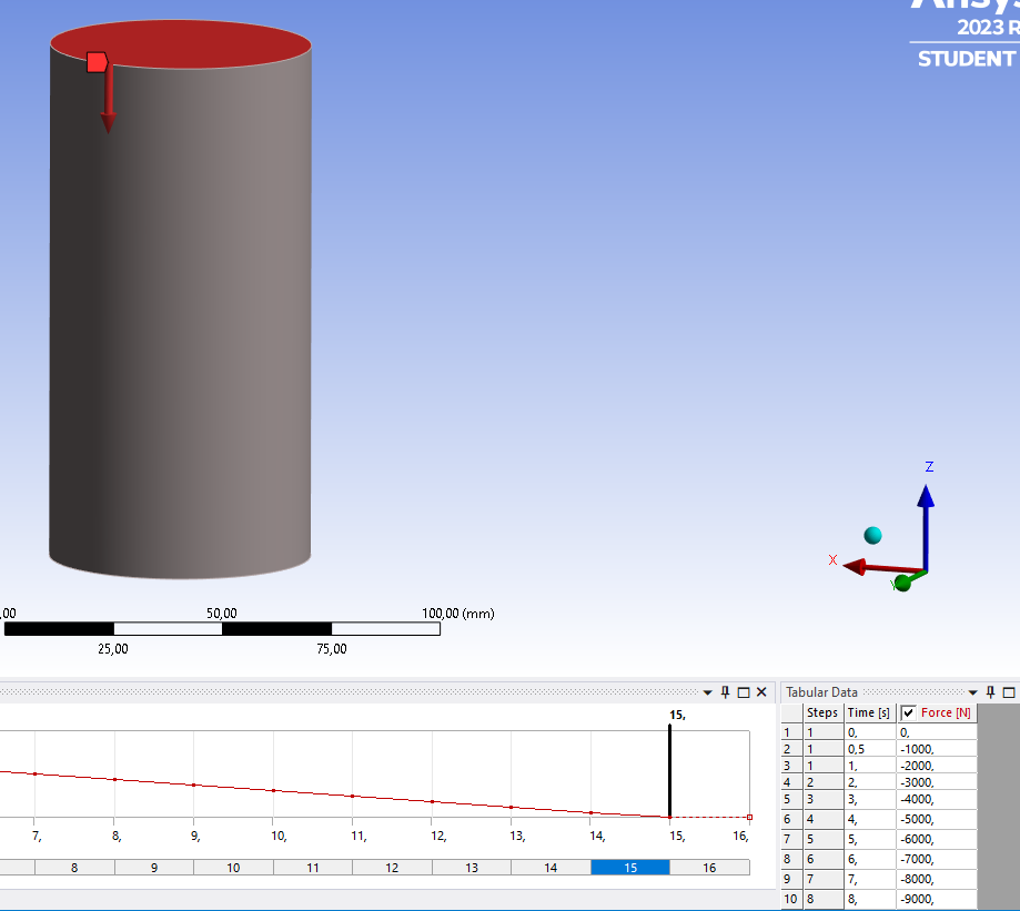
Boundry condition: fixed support.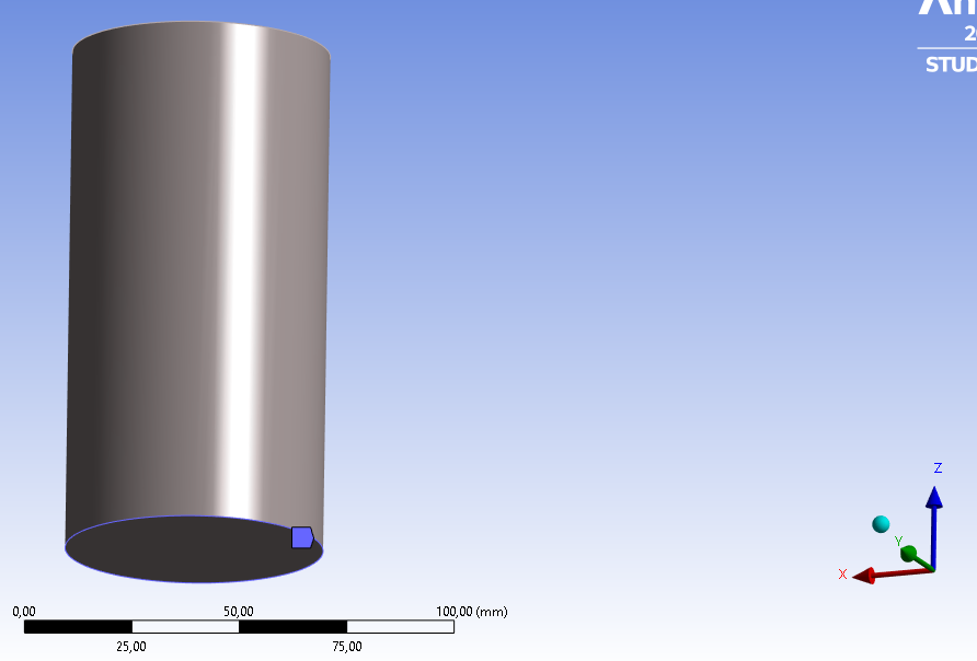
-
March 28, 2024 at 1:45 pm
Armin
Ansys EmployeeHi Maciej,
In the laboratoy tests, was the sample free to expand during the load application? If so, by using “Fixed Support” at the bottom, the sample is likely over-constrained which may explain the discrepancy you’re seeing in the simulation results.
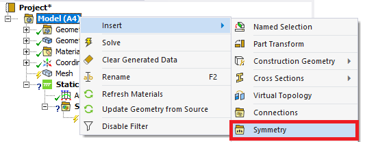
As another suggestion to simplify the model, try exploiting symmetry of the specimen. For example, your case can be simulated using axisymmetric assumption. If you’d like to model it in 3D, try cutting the specimen and using symmetry regions (screenshot below).
-
March 28, 2024 at 1:52 pm
Maciej Wojdowski
SubscriberHi, Armin, many thanks for the reply.
the picture shows the testing apparatus.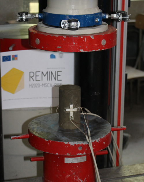
So I,ve tried modeling also the bottom plate
And bottom plate of the testing machine is fixed, and cylinder is just lying on top with contact as below:
But still this gives me wrong results.
I think modeling symetry is gonna be a good idea, maybe the solver will run faster. Do you know also if i specified material correctly and if I correct my mistakes in boundry conditions, the material data will still be sufficient to obtain 10-20% similarity in results?
Maybe instead of modeling the bottom plate of the apparatus I should do place "displacement" for the bottom part of the cylinder and free x,y directions and fix only Z?
-
-
March 28, 2024 at 3:08 pm
Armin
Ansys EmployeeThanks Maciej,
The contact type is set to "bonded" in your screenshot. I think it is more realistic to switch it to "Frictional" with an appropriate coefficient of friction. The bonded type will not allow the faces of the sample to slide relative to the compression plates and will have a similar effect as using fixed support you used earlier.
Since you're considering the bottom plate, I think it is more realistic to also consider the top plate with similar contact properties. You may assume the stiffness behavior of the plates to be "rigid" to reduce the computational time.
-
March 28, 2024 at 3:26 pm
Maciej Wojdowski
SubscriberArmin, thank you very much for your help.
After some research I think If i add the top plate of the test machine I think i should then use explicit dynamics module and instead of using a force - I should use a displacement (which unfortunately I don't how much the press moved)? Please correct if Im wrong but I dont think just applying the force on the top plote of the machine would transfer the load realisticly to the sample?
I've tried to do explicit dynamic analysis before with 2 plates from the machine (top was displaced on -z axis for 1mm) but the solver couldnt compute due to convergance error.
Maybe you can suggest which analysis and loading (force or displacement) should be used here?
-
March 28, 2024 at 5:06 pm
Armin
Ansys EmployeeThat's a good plan Maciej. The explicit dynamics solvers should be able to handle this problem. Try applying velocity-based boundary conditions in explicit dynamics (AUTODYN or LS-DYNA) instead of load and then compare the resulting stress-strain curves with those of the experiment.
If you face any difficulties, you can post it here or start a new forum post and someone will be able to help you.
If you need a good learning resource about the theory of explicit dynamics analysis, checkout out the following lesson: Explicit Dynamics Theory - Ansys Innovation Course - YouTube
-
-
-
- The topic ‘Geopolymer modeling Problem’ is closed to new replies.


-
4678
-
1565
-
1386
-
1241
-
1021

© 2025 Copyright ANSYS, Inc. All rights reserved.

