TAGGED: dof-contraints, substructuring
-
-
October 18, 2024 at 4:19 pm
reddyramu.gundlooru
SubscriberHello,
My name is ReddyRamu, I have a problem regarding substructure generation. I´m a student writing a master's thesis on a journal (EHD) bearings using AVL EXCITE M. For this I need to prepare a substructure file which could be later imported to AVL EXCITE. I could generate an EXB file for bearing wall without any issues. But, for bearing pin/journal there is an issue. I could generate the EXB file but with some warnings. I think this is because I defined the interface points of the bearing pin with MASS21 elements with negligible inertias as recommended.
After meshing I had to define some interface points (master nodes) in the center of the journal. These interface nodes should be defined with MASS21 elements with KEYOPT(3)=0, negligible mass, and rotational inertias.
.png)
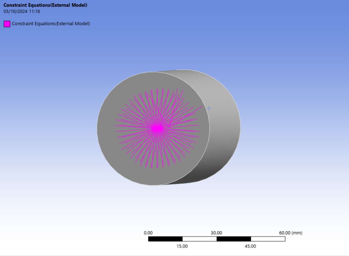
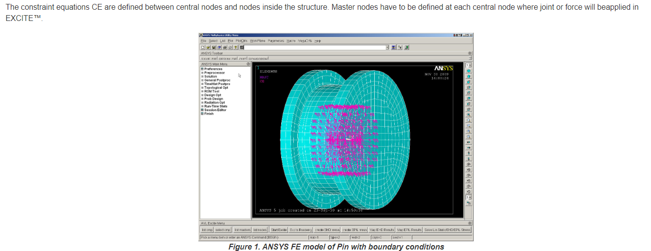
Later I need to generate constraint equation CE/CERIG to connect these interface nodes to the surrounding slave nodes. I did all this in Mechanicl APDL


and later imported it to the workbench to generate an EXB file using the APDL command. but When I imported the CDB file (APDL) to Workbench, there was an undefined component
point mass..png)
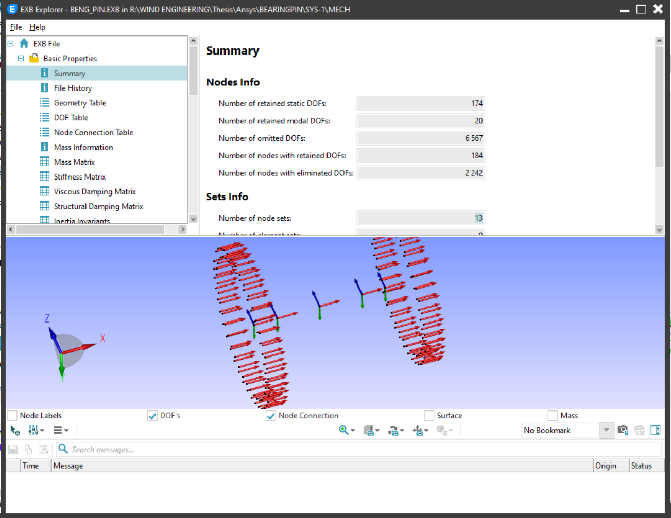
I wasn´t sure how to fix it so I just suppressed it and ran the script. It created an EXB file but, when I imported the EXB file in EXCITE, I was missing all the rotational DOFs at interface points. as you can see all this in the below pictures.
If possible could anyone help me to define the CEs between center and slave nodes correctly?
Thank you!
Reddyramu Gundlooru
-
October 22, 2024 at 8:44 pm
dlooman
Ansys EmployeeBy giving the mass21 a small rotational inertia in all directions, the master node will have all 6 dof. Then CERIG,master node, all,all should write constraint equations for all the selected nodes in terms of the master node ux, uy, uz, rotx, roty, rotz. You should confirm this before leaving APDL with celist. Because the master node dof are retained they can all be used as the master dof of a superelement. I don't know what the error message means, but you could avoid the issue by defining the mass in Mechanical use the Rigid behavior.
-
October 30, 2024 at 6:09 pm
reddyramu.gundlooru
SubscriberHello Dlooman,
Thank you so much for your response. The problem was fixed when I created a new node at the same position as the intended node and used it for the MASS21 element instead of using the existing mesh node. But some new warning was raised when I created a superelement as you can see in the attached image. There are no issues with the DOFs of the master node but all the rotations DOFs are missing for the slave nodes.
I have got one more problem during the import of the CREO Parametric part into APDL as you can see in the picture below.
If possible can you please help me with these issues?
Thank you and best regards
Reddyramu Gundlooru
-
October 30, 2024 at 8:39 pm
dlooman
Ansys EmployeeYou can ignore those warning messages. They just mean the slave nodes don't have rotational dof. You could issue cerig,,,uxyz to get rid of the messages. I can't help too much with the 2nd problem. Does the anf file actually exist? Are you in the right directory?
-
December 5, 2024 at 5:25 pm
reddyramu.gundlooru
SubscriberHello Dlooman,
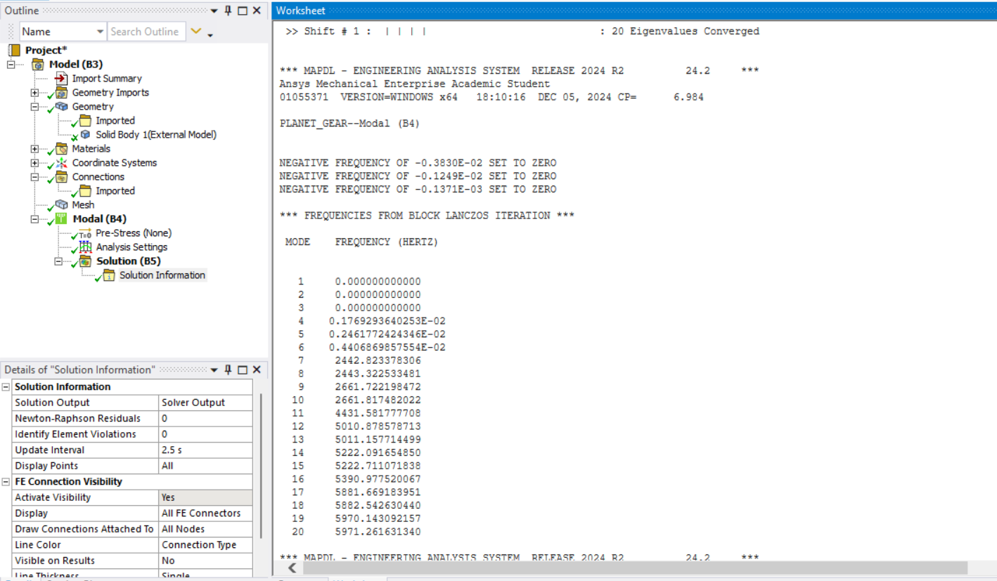
During substructuring, I have a problem with eigenfrequencies. For example, I´m doing substructuring for a gear wheel. After condensation, the eigenfrequencies are not as expected as you can see in image 1 but i removed constraint equations and mass elements then i got proper frequency values as you can see in image 2. Can you please help me with this problem?
-
December 5, 2024 at 6:07 pm
dlooman
Ansys EmployeeIn image 1 I see you have over 65,000 equations. Are those all master dof of the condensed part? Are there warning or error message in the solution information output? Perhaps you can tell from the mode shapes why you aren't getting 6 rigid body modes.
-
January 26, 2025 at 10:47 pm
reddyramu.gundlooru
SubscriberHello,
I´m having trouble generating the substructuring. I used the RBE3 command to define a rigid region center node to surrounding slave nodes for a rotating shaft. for interface points(master nodes) i used MASS21 with negligible mass and inertias. But when i imported my model from APDL to workbench and ran substructuring analysis, I got an unknown error as you can see in the image 3. If possible, Could you please help me with the issue?
Thank you and best regards
Reddyramu Gundlooru
-
January 27, 2025 at 3:54 pm
dlooman
Ansys EmployeeIt's odd to get a pivot error in a modal analysis since the rigid body modes represent a zero pivot and are acceptable. Perhaps you have a body without any mass?
-
January 28, 2025 at 12:52 pm
-
January 28, 2025 at 4:05 pm
dlooman
Ansys EmployeeThat message means you have some of the degrees of freedom in your constraint equation were not available due to having been removed from the active dof set by displacement constraints or other constraint equations.
-
January 28, 2025 at 7:20 pm
reddyramu.gundlooru
SubscriberHello,
Thank you for your reply. Can you please help me how to solve this issue?
Thank you!
-
- You must be logged in to reply to this topic.


-
4969
-
1645
-
1386
-
1242
-
1021

© 2026 Copyright ANSYS, Inc. All rights reserved.


.png)
.png)
.png)
.png)


