TAGGED: ansys-fluent-meshing, cad-import, cell-zone, sliding-mesh, sphere
-
-
December 11, 2024 at 3:19 pm
Nathaniel
SubscriberHi, I am trying to perform an external flow analysis of a rocket. To find the damping, I need to run transient pitching and rolling simulations. I am using a sliding mesh approach. However, I cannot get Ansys fluent meshing to detect the face zones properly and create a non-conformal mesh, specifically when the moving domain is a sphere. Everything works correctly when the moving domain is a cylinder.
My method for generating the geometry consists of the following:
- Use create enclosure on rocket body to create spherical or cylindrical moving domain.
- Move the solid out of the enclosure component and rename to movingDomain and delete the empty component.
- Use create enclosure on 'movingDomain' solid to create staticDomain.
- Move the solid out of the enclosure component and rename to 'staticDomain' and delete the empty component.
- Delete/hide and suppress the original rocket body
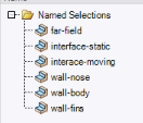
- Create named selections:
- Outside faces: 'far-field'
- 'staticDomain' inner face(s): 'interface-static'
- 'movingDomain' outer face(s): 'interface-moving'
- 'movingDomain' object faces: 'wall-xxx'
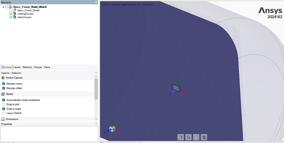
Below are the results of this process when using a sphere as the internal sliding mesh interface or a cylinder as the interface.
- Next I use the workbench->fluent 2024 R2->watertight workflow button to move to fluent meshing.
- The difference between the two cases appears when running the 'generate the surface mesh' task.
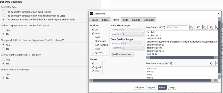
- For the sphere case, a new face zone is auto-created called far-field:xxxx, and no 'generate non-conformal mesh' option is available under describe geometry task
- This far-field:xxxx face zone remains throughout the rest of the process and then causes issues when switching to solution mode as far-field:xxx face zone is the same as the 'interface-static' zone. Basically, somehow, an extra face or face selection is created on the sliding mesh interface. Which results in an extra boundary.
- This also happens when selecting the share topology option in fluent meshing OR selecting share topology in SpaceClaim or Discovery before importing. (I tried this even though I need a non-conformal mesh for the sliding mesh analysis)

- When clicking generate surface mesh task in the cylinder case:
If anyone has an idea why there might be a difference between these two cases, please let me know. It seems like a bug or error to me. The only difference I can think of is that in the case of the cylinder interface, there are a number of edges present, while in the case of the sphere, there are no edges. While waiting for a reply, I will try imprinting an edge on the sphere to see if that changes the results.
Using a sphere as an interface is rather important for me as I need to be able to rotate the inner sphere in arbitrary directions. Generating a new mesh with a cylinder perfectly matching each angle would be basically impossible.
Please note that I have also tried several different ways of generating the same input geometry. For example, I created the whole enclosure and sphere and then used the combine tool, or I manually created every solid. Either way, the results are the same.
-
December 12, 2024 at 10:14 am
Rob
Forum Moderatorhttps://innovationspace.ansys.com/forum/forums/topic/generating-non-conformal-mesh-for-sliding-mesh-when-moving-domain-is-a-sphere/
https://innovationspace.ansys.com/forum/forums/topic/generating-non-conformal-mesh-for-sliding-mesh-when-moving-domain-is-a-sphere-3/
Posting in three different channels won't get you a faster response. It does however get a mildly annoyed moderator. Consider this my friendly warning.
-
- The topic ‘Generating non-conformal mesh for sliding mesh when moving domain is a sphere’ is closed to new replies.


-
4678
-
1565
-
1386
-
1241
-
1021

© 2025 Copyright ANSYS, Inc. All rights reserved.


