-
-
August 21, 2024 at 8:07 am
sudhakar917
SubscriberDear peteroznewman
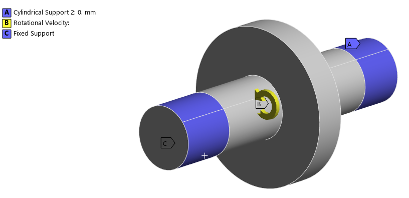
I would like to estimate the gear tooth deformation due to rotational velocity along x, y and z directions.
The gear/pinion is supported by journal bearings.
Boundary conditions: 1. Cylindrical support in the location of journal bearings. Radial = fixed, Axial = Fixed and Tangential = Free
2. Rotational velocity applied to the shaft (rpm).
Could you please tell us, whether the boundary conditions given are correct or not? Is there any other method to estimate the gear teeth deformation due to rotational velocity or centrifugal effect.
Regards,
Sudhakara
-
August 21, 2024 at 12:38 pm
-
August 23, 2024 at 4:08 am
sudhakar917
SubscriberHi experts,
The pinion shaft is supported by journal bearings on either side (but we have given cylindrical support). Whether the type of bearing support will affect the pinion tooth deformation?
The pinion shaft is an integral one (there is no separation between shaft and the wheel as in the case of gear wheel shafts).
Is the fixed support possible here?
Please suggest a method to accurately estimate the gear/pinion tooth deformation.
Thanks,
Sudhakara
-
August 23, 2024 at 9:44 am
-
August 27, 2024 at 5:51 am
sudhakar917
SubscriberHi experts,
Could you please clarify the statement mentioned by you earlier i.e., “If you give both cylindrical supports, the model won’t be in static equilibrium”.
The left end of the rotor shaft is coupled to other devices like motor. As mentioned earlier, the rotor is supported by journal bearings. As we are not able to define the bearing properties for journal bearing, we have used cylindrical supports on both ends.
Whether the methodology followed for estimating the tooth deformation is correct or not?
Do I need to define the journal bearing properties to estimate the tooth deformation correctly?
Please clarify.
Regards,
Sudhakara
-
August 27, 2024 at 7:02 am
Deepak
Ansys EmployeeBy giving only cylindrical support, the model will be in continuous motion.
-
-
August 27, 2024 at 8:49 am
sudhakar917
SubscriberHi Deepak,
I have used one end fixed support and other end cylindrical support. The total deformation of gear tooth is 90 microns.
I have used journal bearing stiffness and damping properties on both ends (k11,k12,k21,k22, c11,c12,c21,c22). The total deformation is given as 220 microns.
Which one is correct?
Please help me out.
Sudhakara
-
August 29, 2024 at 5:34 am
Deepak
Ansys EmployeeUsing fixed-end and cylindrical support gives the combined effect of twisting and centrifugal forces.
Both cylindrical supports cause deformation due to centrifugal forces.
-
-
August 29, 2024 at 10:54 am
sudhakar917
SubscriberDeepak,
I have used cylindrical support in the place of journal bearings. Is it correct to use?
or Do I need to use journal bearing stiffness and damping properties to get exact value of deformation?
Please clarify.
Thanks,
Sudhakara
-
August 29, 2024 at 11:01 am
Deepak
Ansys EmployeeCylindrical support can be used to represent bearing behavior in some cases, but for precise deformation and dynamic analysis, incorporating the specific stiffness and damping properties of journal bearings is recommended. These properties are crucial for accurately calculating the dynamic behavior of the system.
-
-
August 29, 2024 at 11:20 am
sudhakar917
SubscriberWhat stiffness value (N/m) will be considered for cylindrical support in ansys workbench?
-
August 29, 2024 at 11:42 am
Deepak
Ansys EmployeeCylindrical support in ANSYS, this boundary condition prevents the cylindrical faces from moving or deforming (fixed or free) in combinations of radial, axial, or tangential directions, which does not inherently include a stiffness value.
Refer: 17.6.3.7. Cylindrical Support (ansys.com)
Thanks
-
-
- You must be logged in to reply to this topic.


-
5179
-
1836
-
1387
-
1249
-
1021

© 2026 Copyright ANSYS, Inc. All rights reserved.


