TAGGED: compression, gasket, metal
-
-
February 9, 2024 at 12:05 pm
Georgios Panagiotopoulos
SubscriberHi everyone,
I am currently working on my Master's thesis and I am attempting to simulate the compression of a thin metal plate (gasket) between two diamonds. This compression should result in a bulge forming as the material is displaced and strained as in the following image.
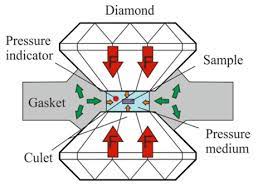
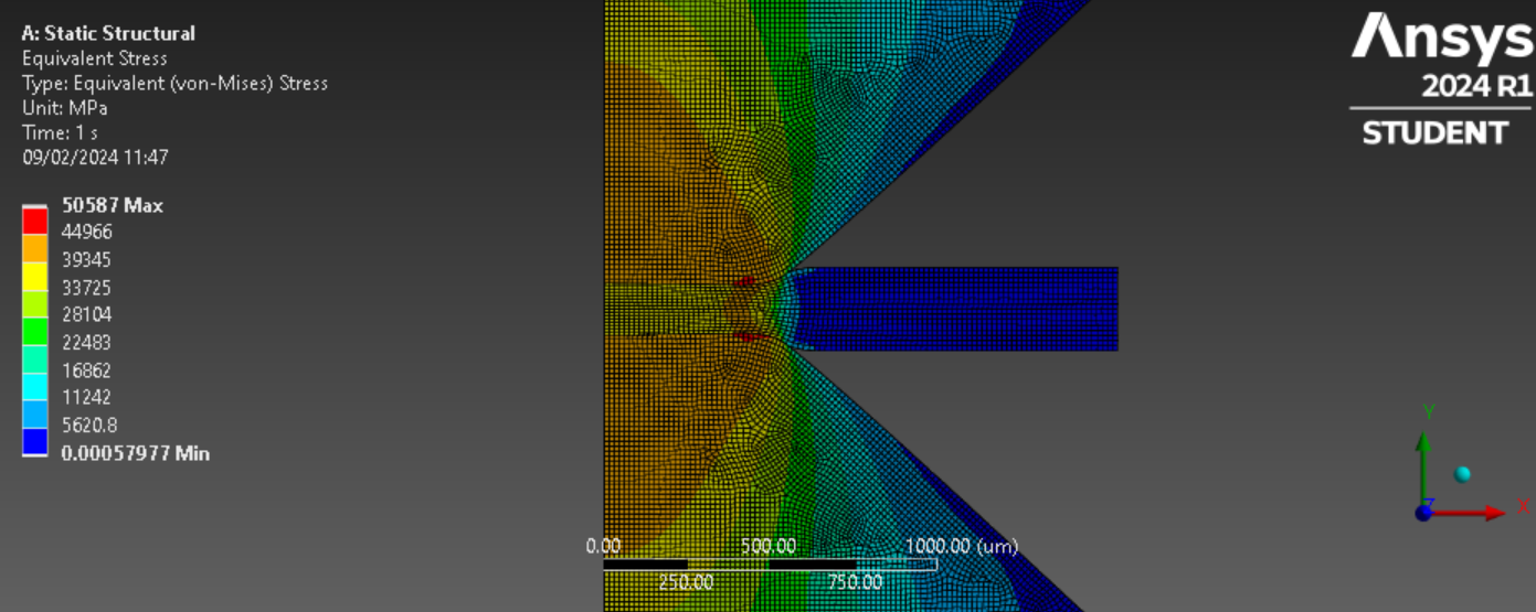
My simulation is providing the following results and no bulge is forming, any advice? Thank you!
-
February 9, 2024 at 1:58 pm
peteroznewman
SubscriberIt looks like you could cut the geomety in half about the horizontal center plane and use a symmetric boundary condition (Y=0) on that cut face.
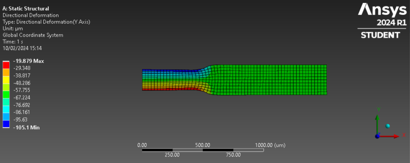
Please plot the Directional Deformation in the Y axis for the metal plate only. That will be the best plot to look for a bulge.
I assume you have a plasticity material model in Engineering Data on the metal. If not, that is required to get a good sized bulge.
-
February 10, 2024 at 3:18 pm
Georgios Panagiotopoulos
SubscriberHi Peter,
Thank you very much for your help! Here is the plot of the directional deformation of the plate:
In a different sim, I added Multilinear Isotropic Hardening to include plasticity, but it did not make the gasket bulge. Any other suggestions? I was thinking of maybe running the model in LS-DYNA and seeing if that solves the problem.
-
February 10, 2024 at 5:09 pm
peteroznewman
SubscriberHi Georgios,
I see evidence of the outward flow of material from the squashed zone by the curvature of the element columns. You could see this effect clearly by plotting the Directional Deformation in the X direction.
If you take my previous advice and split the model about a horizontal center plane, then nodes on that plane will have a zero Y axis directional deformation and the top surface will only be a small negative value instead of the entire gasket having large negative values.
Perhaps the cartoon illustration of the "bulge" you are looking for is an inaccurate description of what really happens. Since this model is converging, you don't need to run the model in LS-DYNA.
-
February 10, 2024 at 10:45 pm
-
February 11, 2024 at 1:23 pm
peteroznewman
SubscriberHi Georgios,
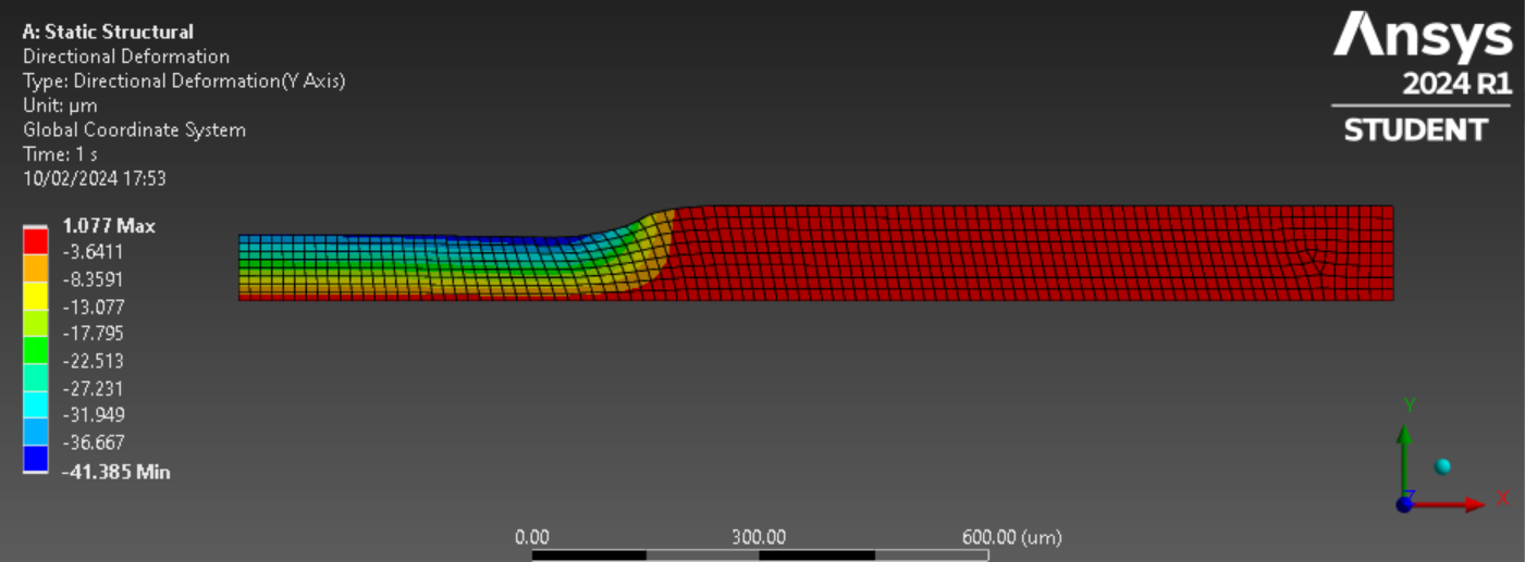
Great, one last tweak to the Directional Deformation (Y-Axis) will give you the clearest view of the "bulge". Double click on the -22.513 value in the legend and type a 0. Double click on the green-blue box below that number and change that color to purple. Now the edge between green and purple is the contour of zero thickness change. All the colors from green to red represent an increase in thickness, which you could call a bulge if you like. All the colors from purple to blue represent a decrease in thickness.
-
February 16, 2024 at 3:30 pm
Georgios Panagiotopoulos
SubscriberHi Peter,
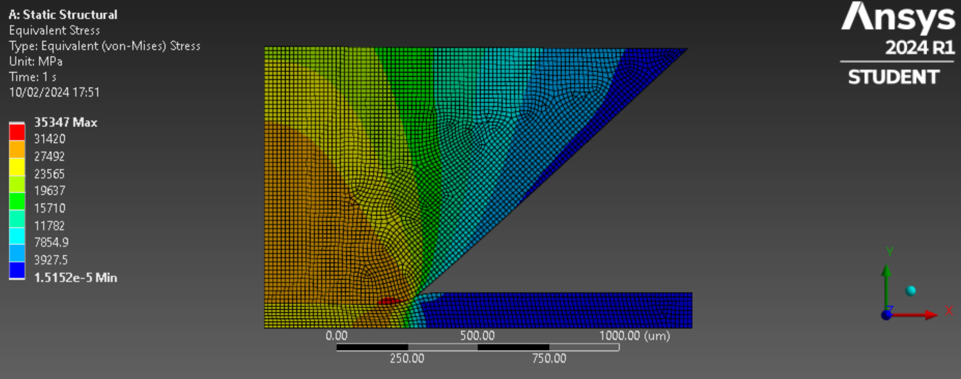
Thank you for the great advice. That helped a lot! However, the increase in thickness is only about 1 micrometer, which is negligible compared to the 250 micrometer thickness of the gasket. In order to increase the thickness of the bulge I attempted to compress the gasket further, but when I compress it by more than about 150 micrometers, the simulation fails like in this image:
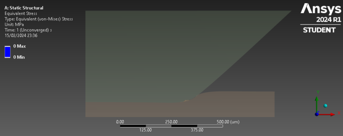
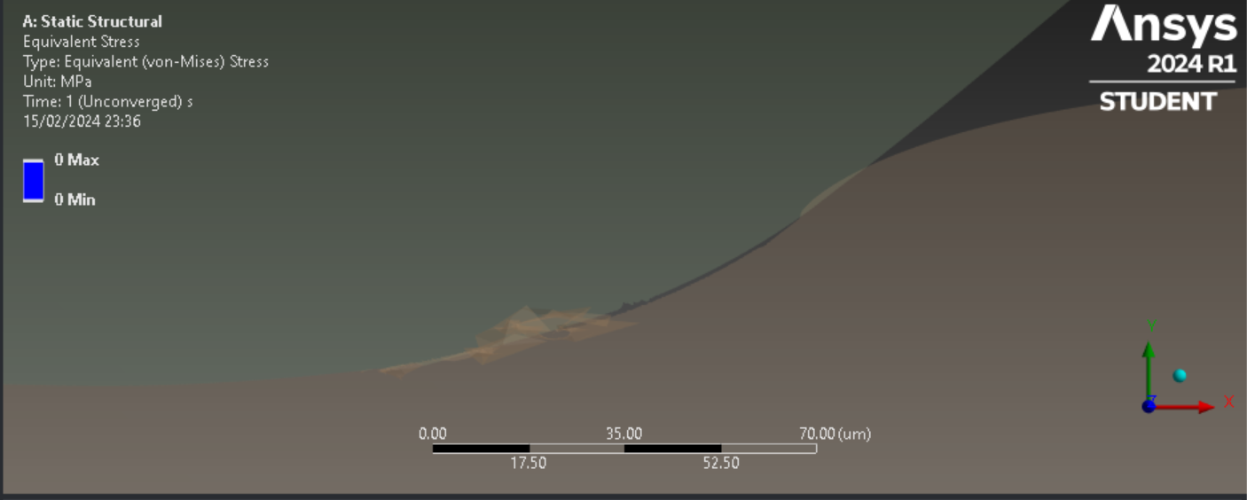
Do you have any advice for this? Hope you have a great day.
-
February 16, 2024 at 10:19 pm
peteroznewman
SubscriberForcing the solver to take more small substeps often helps. Therefore increase the Initial and Minimum Substeps by a factor of 10 or more. Increase the Maximum Substeps by a factor of 100.
Softening the Normal Contact Stiffness by a Factor of 0.1 may help.
-
February 19, 2024 at 5:48 pm
Georgios Panagiotopoulos
SubscriberHi Peter. I tried both of your suggestions, however, the model still does not converge. Would something like LS-DYNA be required for this case? A further issue I am having is that when I set a displacement of half the gasket thickness, for example, the gasket is only compressed by 20-30% rather than 50%. Thank you again for your support!
-
February 19, 2024 at 7:42 pm
peteroznewman
SubscriberHi Georgios,
When convergence becomes extremely difficult, LS-DYNA or Explicit Dynamics can be used to overcome the convergence issue because every time step is automatically a converged time step by design. However, you will encounter new challenges brought on by the nature of the solver. Every change in load produces elastic waves that travel through the body at the speed of sound. The requirements of meshing change as the mesh size has to accomodate 6 quadratic elements in one wavelength of the sound wave. The automatically defined time step depends on the smallest element size, so you don't want to allow unusually small elements to be created.
Before you go to an explicit solver, have to tried some Stabilization methods in the implicit solver? Read some of the discussions that are linked in this Google Search result.
-
March 11, 2024 at 1:07 am
Georgios Panagiotopoulos
SubscriberHi Peter,
I have managed to improve the convergence problem by applying the Nonlinear Adaptive Region tool. After doing physical tests in the lab, I measured a 10% increase in thickness around the indentation area when the centre was indented to 50% of the original thickness, but the simulations are showing only about a 1% increase in thickness. Do you have any advice on how to make the simulations yield the same results as the experiments? Thank you again!
-
- The topic ‘Gasket Bulge’ is closed to new replies.


-
4803
-
1576
-
1386
-
1242
-
1021

© 2026 Copyright ANSYS, Inc. All rights reserved.

