-
-
August 31, 2022 at 8:29 am
mohammedlaminemekhalfia
Subscriber -
September 15, 2022 at 5:13 pm
Sheldon Imaoka
Ansys EmployeeHi mohammedlaminemekhalfia,
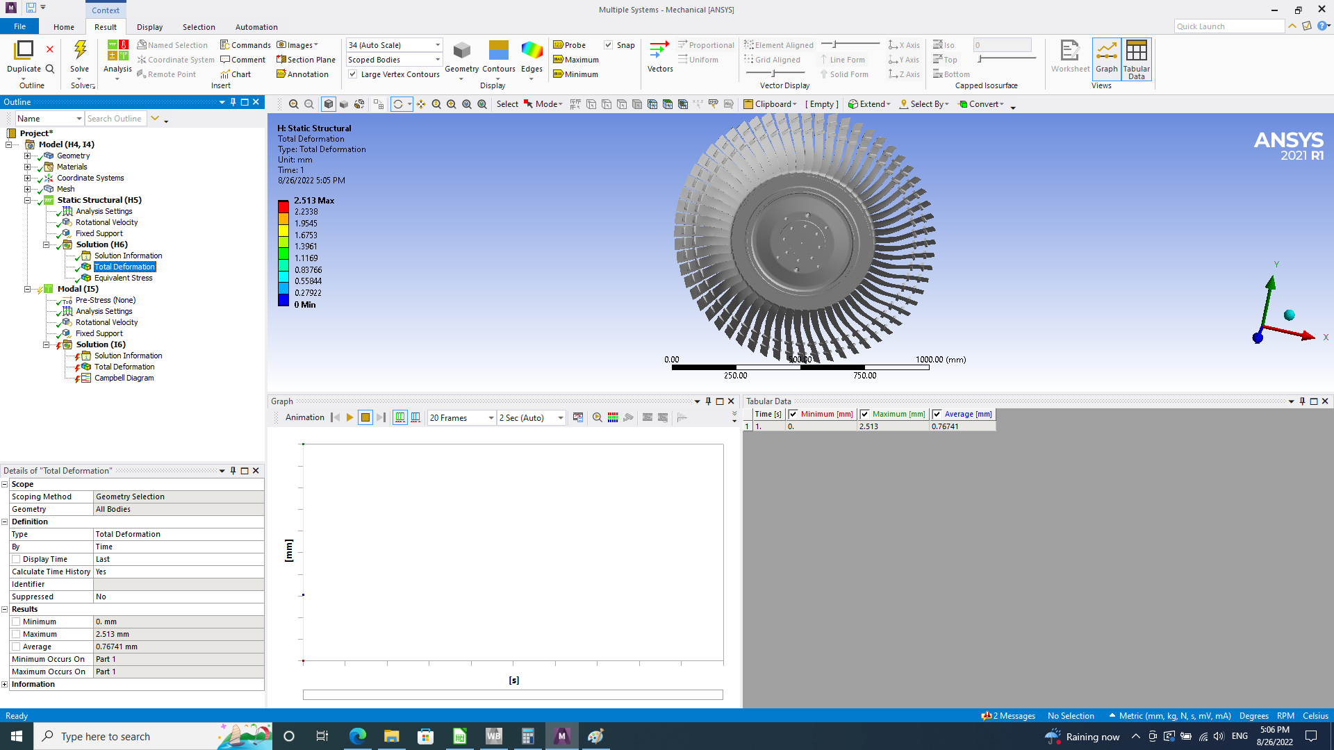
Usually, I believe that Campbell Diagrams are created when you have the disc and shaft - how would you get forward/backward whirls if you are just modeling and constraining the disc? Also, the procedure usually assumes axisymmetric geometry (since the rotating part(s) are not actually rotating).
The Ansys documentation has more details on the assumptions and procedures related to generating Campbell diagrams, so please review that material. (Under "Mechanical APDL" section, "Rotordynamics Analysis Guide")
Regards,
Sheldon-
September 18, 2022 at 12:59 pm
mohammedlaminemekhalfia
SubscriberThanks a lot for the feedback, I was waiting a lot for it.
I read the manual but it say that can not plot campbell diagram for more than 10 modes, even m disc is considered symetric but it has nearly 30 nodal diameter , I did not add the shaft as I consider that the shaft does not have anyi impact on the disc and the damping effect is negligeable !
to plot the campbell diagram for the 3rd mode in my case, I need to extract 2XNDX3 = 180 modes. I do not know if that included in the recent version or the limits on the modes number is still applied, reminding that I am using the simplest rotordynamic case.
again thanks a lot for the feedback.
-
-
- The topic ‘FWD: Problem with Campbell Diagram’ is closed to new replies.


-
4683
-
1565
-
1386
-
1242
-
1021

© 2025 Copyright ANSYS, Inc. All rights reserved.

.png)


