
-
-
November 6, 2021 at 10:19 pm
hesamkeshavarzz
SubscriberIve a shaft whose two ends are hinged by remote disp;acement, why the shaft rotate when I apply a force on its axis???!!!
Project archive file is attached. an image of the shaft is also attached
November 7, 2021 at 7:00 pmpeteroznewman
SubscriberBetter to insert images into your post rather that attach the file because ANSYS staff are not permitted to open attachments.
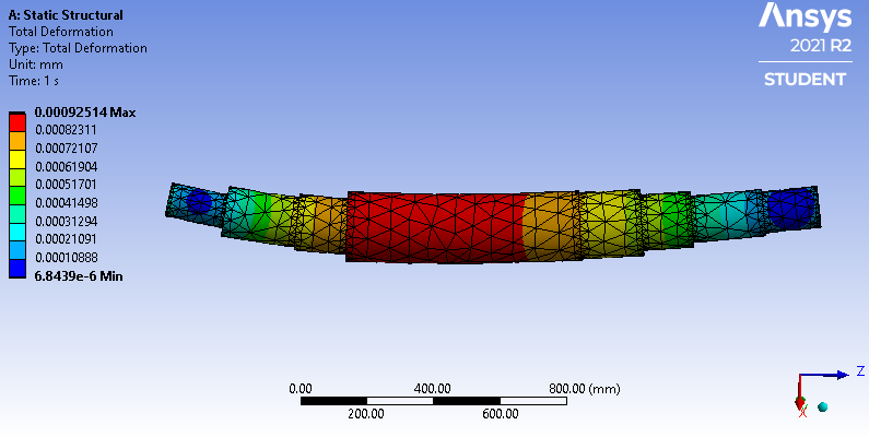
I don't understand why you chose Transient Structural. Wouldn't a Static Structural analysis give you the shaft deflection from this load that you are looking for?
 Why did you turn off Large Deflection?
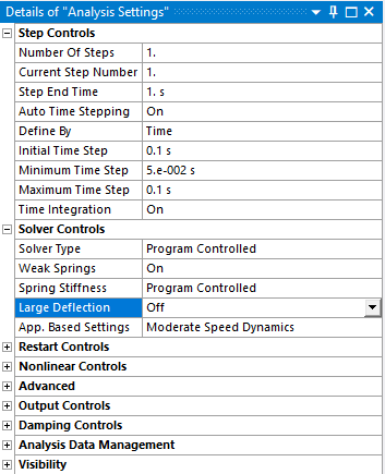 Small rotations cause apparently large deformation, which are not real. If you don't have any rotation in the solution, then you can leave Large Deflection Off.
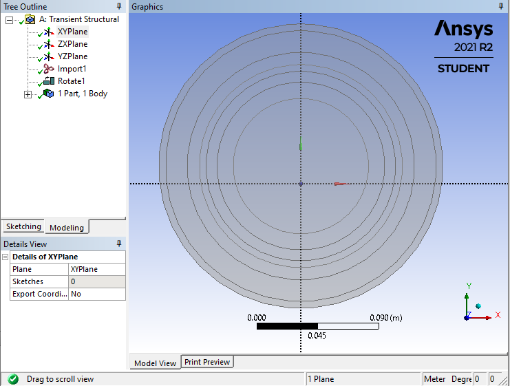
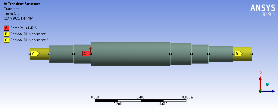
The shaft axis is offset from the global axes in CAD. In this type of model, it is convenient to put the shaft axis on the a global axis.
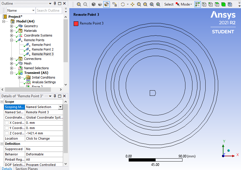
 And the remote points are on the global axis, so they are also offset from the shaft axis.
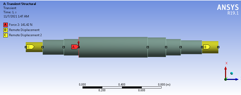
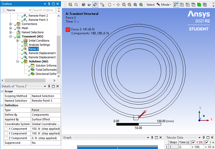
 A force is applied to that the remote point above. Pay no attention to the location of the arrow on the display below, the force goes through the center of Remote Point 3. Why are you applying 100 N in each of X and Y? That makes it difficult to view the results, where the maximum plane of bending is now 45 degrees away from a global plane. I suggest applying 141.4 N in just X and leave Y at 0.
 Two Remote Displacements only constrain X, Y and Z, but do not prevent rotation. This would prevent a Static Structural analysis from solving, which is perhaps why you are solving as a Transient Structural.
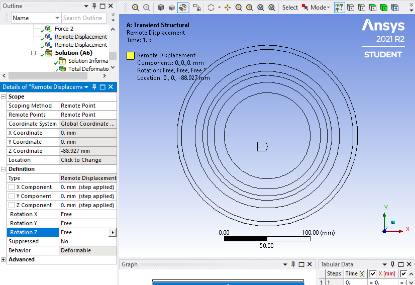 Since rotation is unconstrained in this solution numerical round-off errors can cause the shaft to rotate. Change one or both of the Remote Displacements to have Rotation Z = 0, then you can solve this as a Static Structural analysis.
 November 7, 2021 at 8:20 pmSubscriberHi, Thank you so much for your reply, I want to model unbalance response, considering nonlinear effects, so Ive to conduct transient analysis. with regard to the offset you said, I select the x, y coordinates of the romote points so that there no moment anyway, the problem wouldnt solve, untill I draw the same geometry in ANSYS.
Sincerely
Viewing 2 reply threads- The topic ‘Frustrating rotation!!!’ is closed to new replies.
Innovation Space Trending discussions
- LPBF Simulation of dissimilar materials in ANSYS mechanical (Thermal Transient)
- Convergence error in modal analysis
- APDL, memory, solid
- Meaning of the error
- How to model a bimodular material in Mechanical
- Simulate a fan on the end of shaft
- Real Life Example of a non-symmetric eigenvalue problem
- Nonlinear load cases combinations
- How can the results of Pressures and Motions for all elements be obtained?
- Contact stiffness too big
Top Contributors
-
peteroznewman
 4167
4167 -
scabo
 1487
1487 -
Dennis Chen
 1338
1338 -
javat33489
 1188
1188 -
Shyam Prasad V Atri
1021
Top Rated Tags
© 2025 Copyright ANSYS, Inc. All rights reserved.
Ansys does not support the usage of unauthorized Ansys software. Please visit www.ansys.com to obtain an official distribution.
-


The Ansys Learning Forum is a public forum. You are prohibited from providing (i) information that is confidential to You, your employer, or any third party, (ii) Personal Data or individually identifiable health information, (iii) any information that is U.S. Government Classified, Controlled Unclassified Information, International Traffic in Arms Regulators (ITAR) or Export Administration Regulators (EAR) controlled or otherwise have been determined by the United States Government or by a foreign government to require protection against unauthorized disclosure for reasons of national security, or (iv) topics or information restricted by the People's Republic of China data protection and privacy laws.


