Hello,
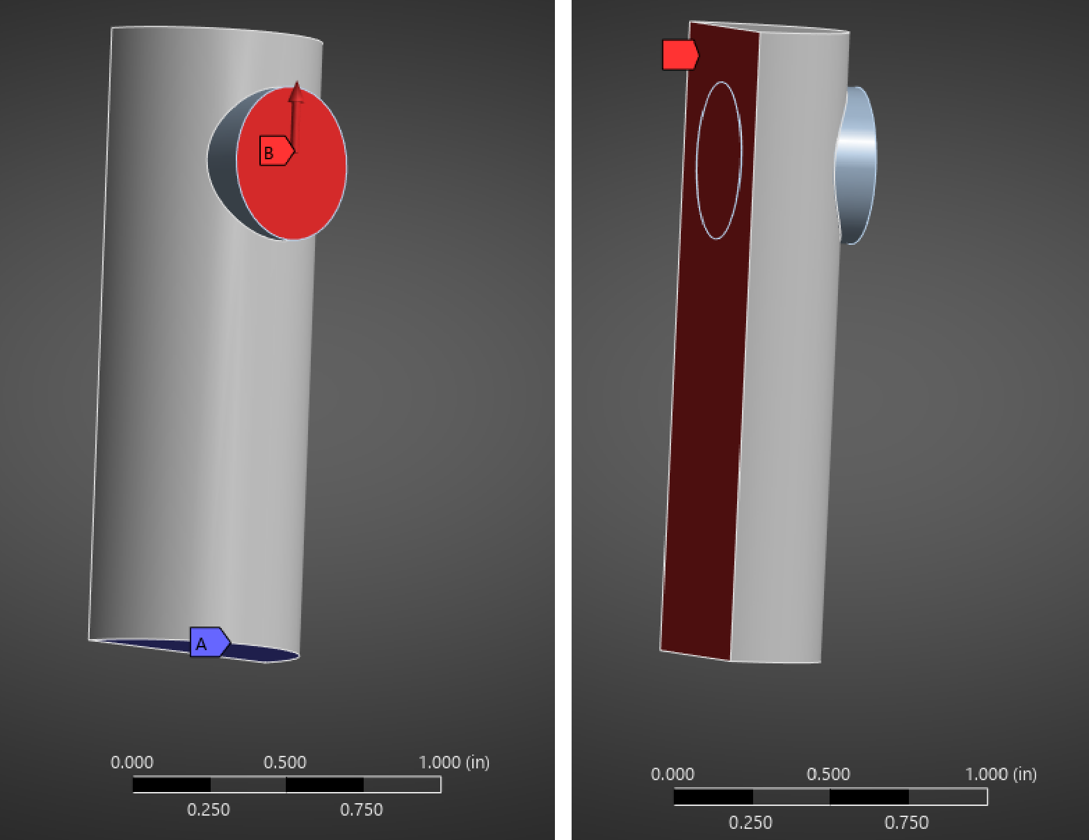
My geometry is a cylindrical steel pin with a section of a steel ring passing through it. The pin has a fixed support at the base, and only a half section is modeled with a symmetry plane cutting the pin along its axis. The ring has a force acting on it such that it should stretch the pin. The contact between the pin and the ring is frictionless. See the images below.
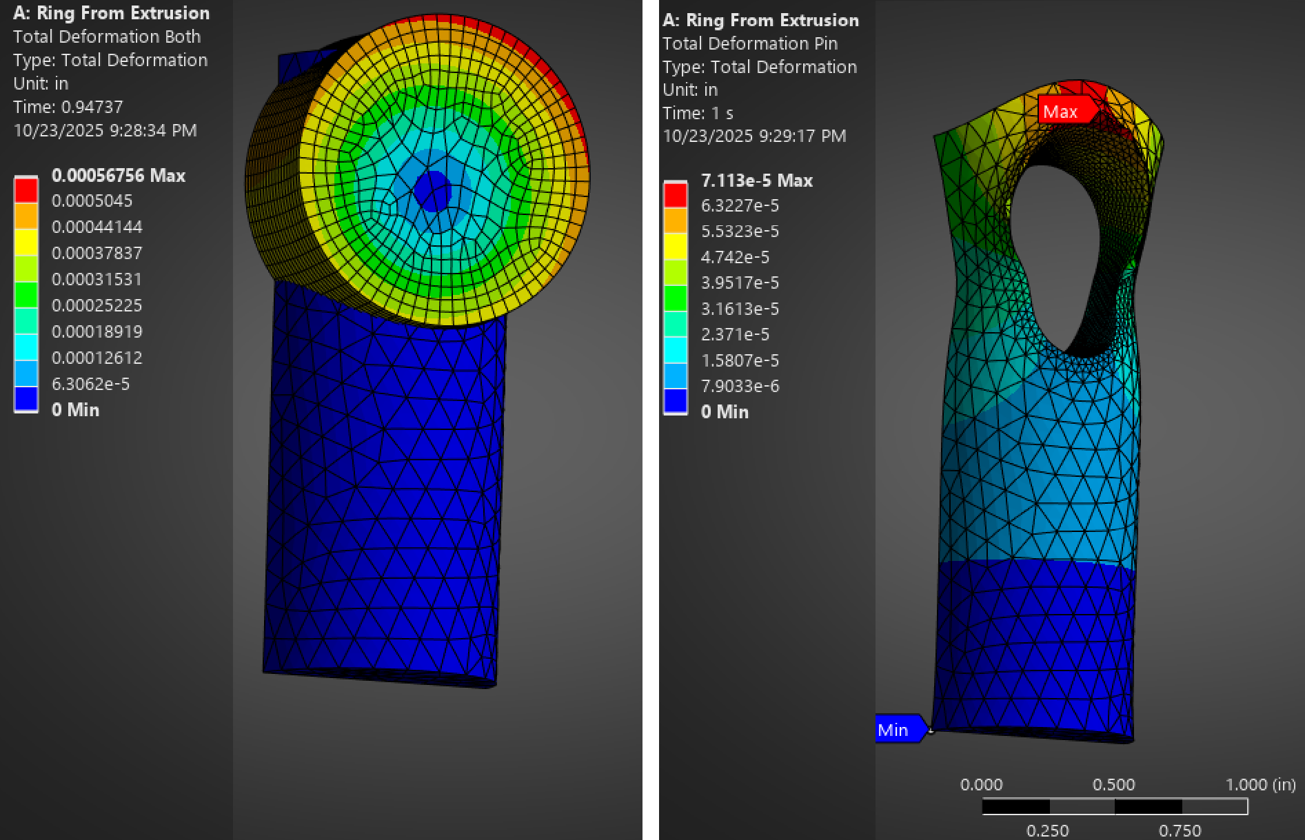
The problems I am facing are two-fold. The first time I tried to model the geometry, I cut the hole in the pin and then made the ring by extruding the circle from the hole on the symmetry side. This ensured a tight fit between pin and ring. When I ran the model, however, the ring did not seem to move in the direction of the force, and instead expanded radially and rotated in place. The strange thing is that the pin still showed deformation of a sort, but why did the ring stop moving and expand? I realize the expansion is exagerated, but why is there any radial expansion to exagerate in the first place? See the below images.
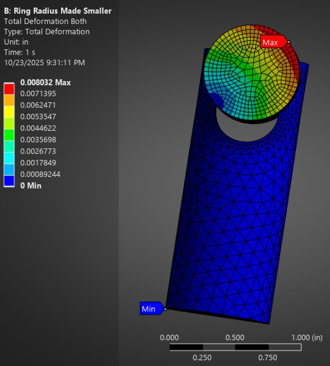
I used the initial contact information tool to try to trouble shoot this issue, and found lots of initial penetration. To remedy this, I used the Pull tool in SpaceClaim to shrink the diameter of the ring by a very slight amount. This resulted in a small gap, which is ok for what I need to do anyway. I tried to have Mechanical account for this by setting a "Stabilization Damping Factor" and setting the Time Step Controls to "Predict for Impact." This did not work, however, as the pin now goes partway past the hole and then, again, expands radially. See the image below:
I am asking for help in both overcoming this issue and also understanding what is going wrong. Here are a few questions I have:
- Why is the ring rotating and expanding?
- Why is the stabilization damping and predict for impact not helping prevent the bodies from penetrating each other?
- Why does the pin show deformation if the ring is passing through it? Is it because only some nodes pass through and the rest "snag" on it?
- I do not want to "Adjust to touch" because in the real system I need to model the ring is even smaller and the local stresses are of interest, so what else can I do here?
- I need the ring to slip freely, be even smaller than I have shown, and stretch the pin. I have tried switching contact and target, refining mesh on the faces of both, and other settings. What am I missing?
These are very simple systems that are meant to capture the behavior I am seeing with a much larger and more complicated project. Since they are small, I will attach an archive that has both of these systems in it. The archive was made with the student 2025 version. Thank you for the help!
StudAndRing.wbpz


