-
-
March 2, 2024 at 5:26 am
m113020070
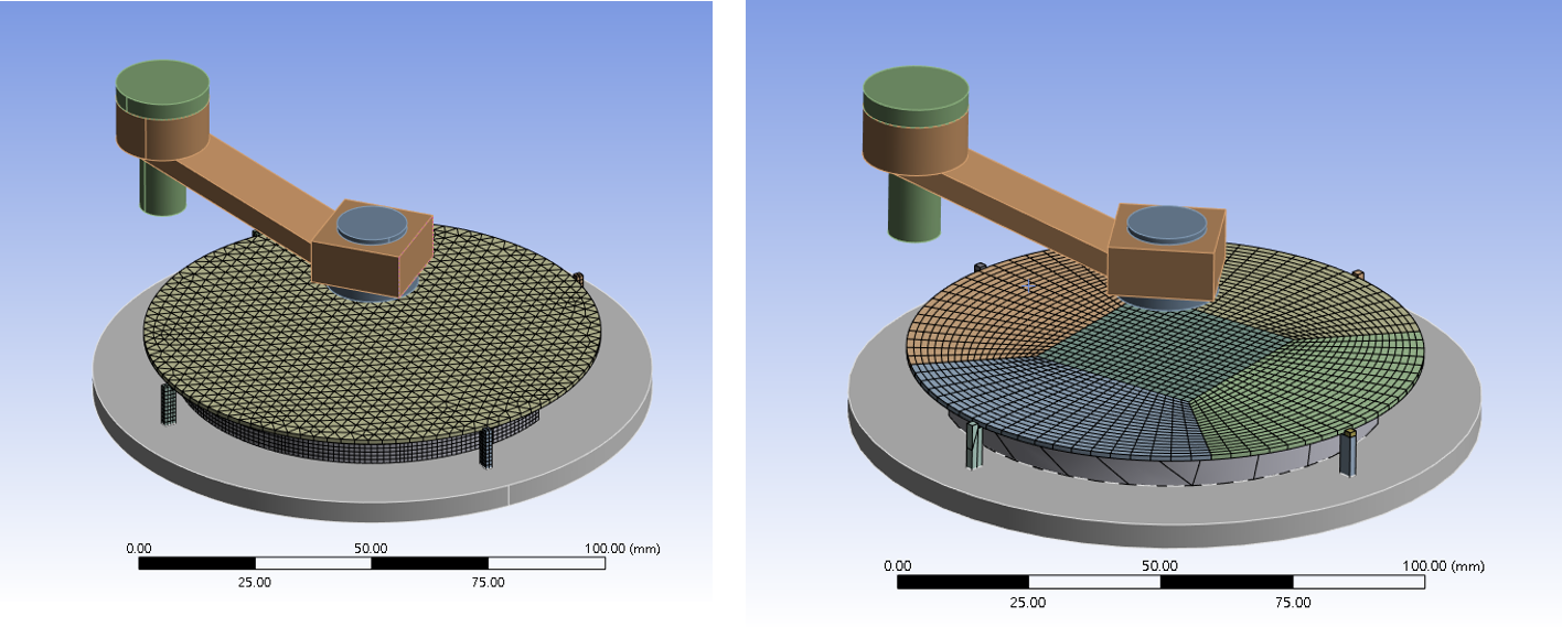
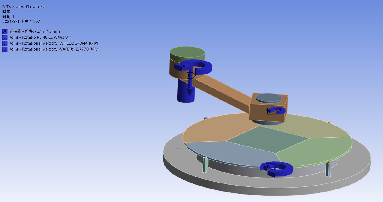
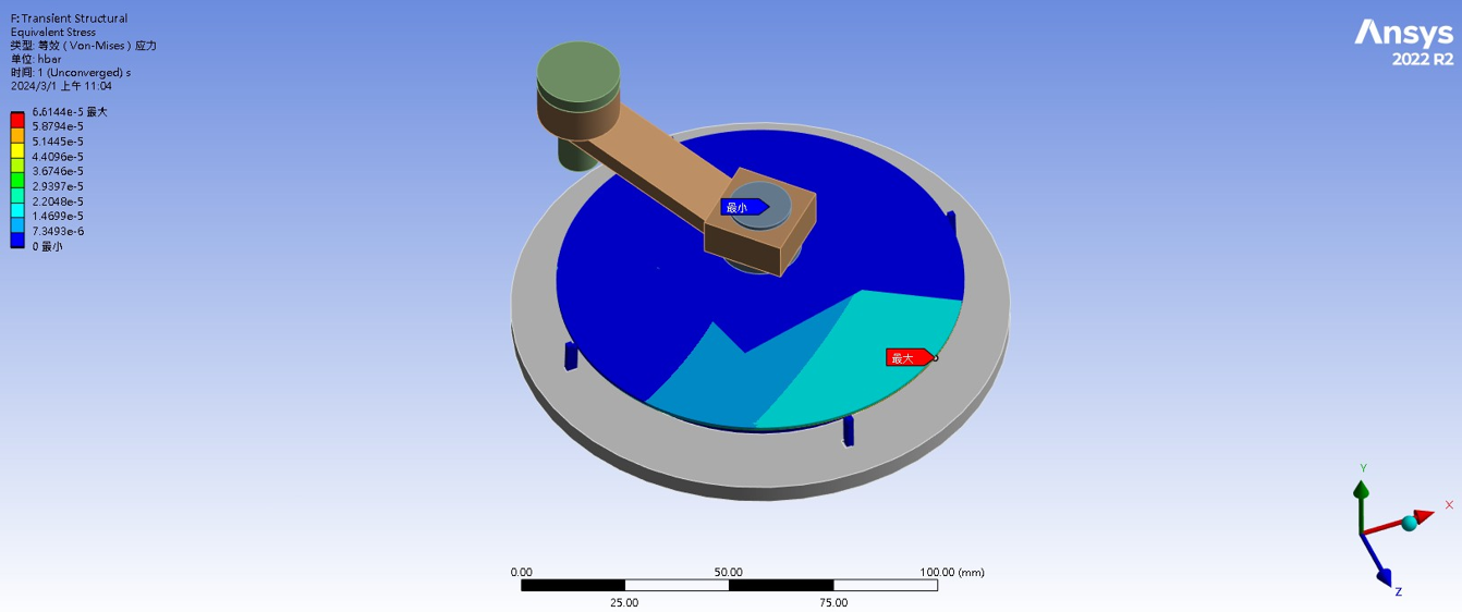
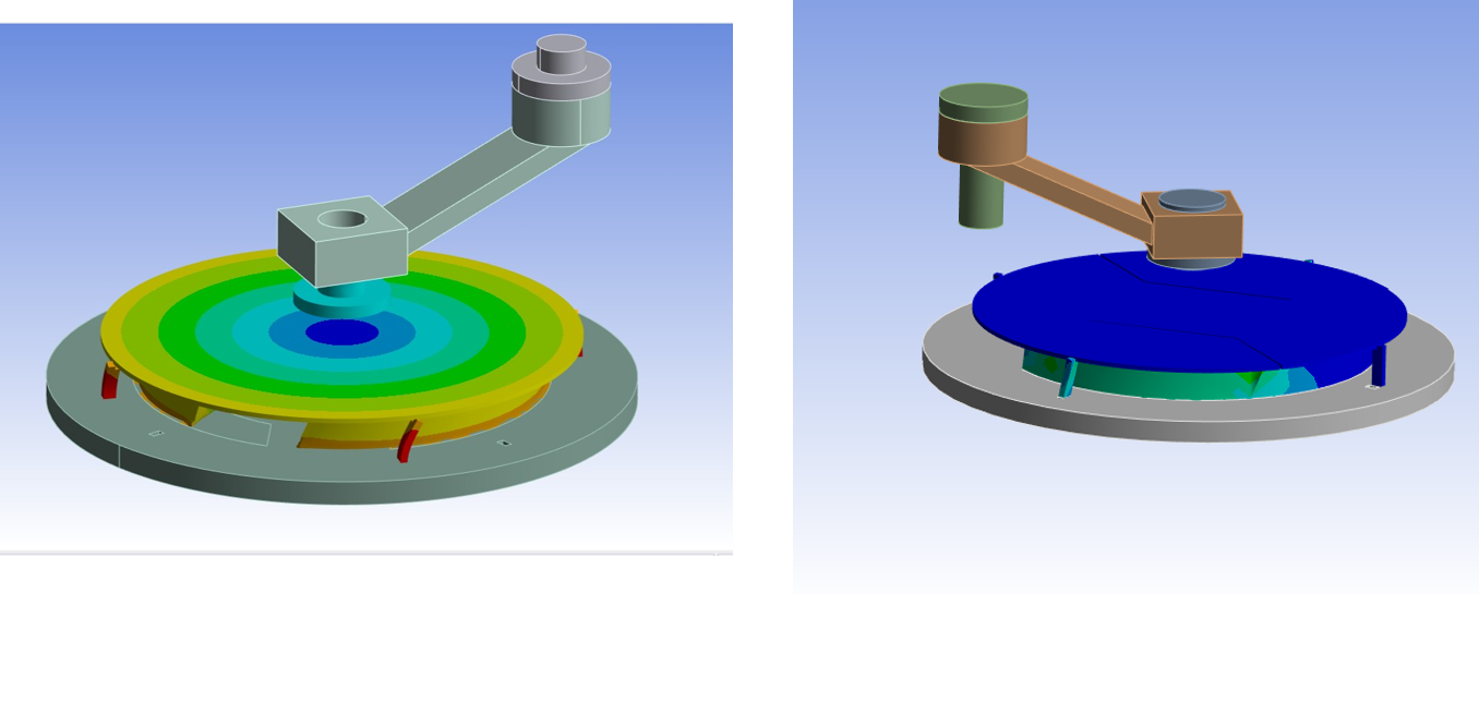
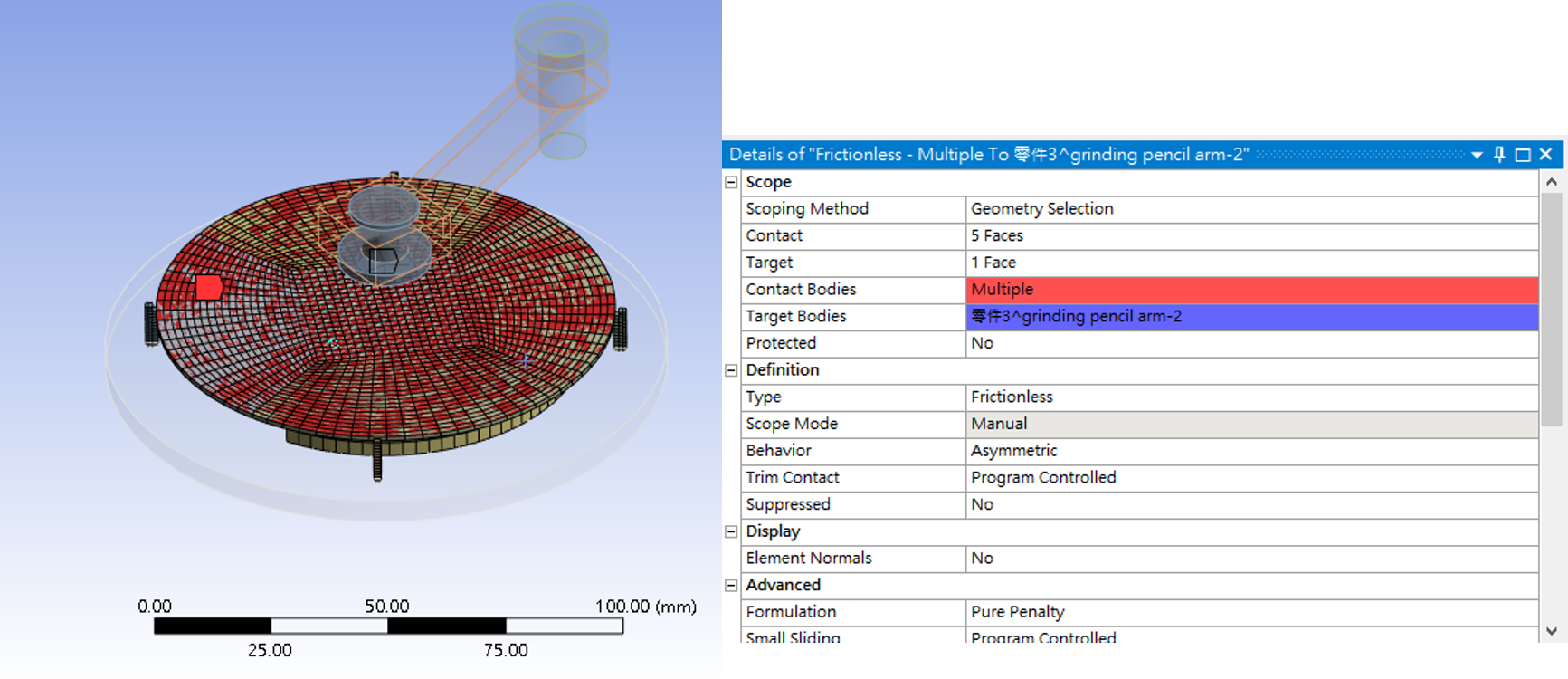
SubscriberDear Guys, nI am trying to simulation of Below are the simulation settings for the grinding part and the questions I would like to inquire about, thank you~~Simulation Settings:Grinding Wheel: Speed: 2200 rpm, Wafer Speed: -250 rpm, Distance between grinding wheel and wafer surface: 11.023mm, The pencil arm rotates 90 degrees from the origin when it contacts the wafer surface.Currently, the number of substeps is set to 200. The grinding wheel and wafer reach the target speed at step 90, the grinding wheel contacts the wafer surface at step 91, and the pencil arm starts rotating from 0 to 90 degrees at step 92.Contact Settings: Rotational parts are set using a revolute joint, and other contacts use bonded contacts. Frictional contact between the grinding wheel and wafer surface uses friction contact with a coefficient of friction set to 0.1.Weak spring and large deflection settings are enabled in the simulation.Rotation of the wafer and grinding wheel is set using rotation velocity; rotation and downward displacement of the pencil arm are set using joint load.Issues:Before optimizing the wafer mesh, severe deformation and detachment of the support frame contact were observed when the process frame at the bottom of the wafer rotated. Substep numbers have been adjusted, and contact settings have been set to bonded, but the issue still persists.When only setting the displacement of the pencil arm downward by 11.023, deformation occurs before the grinding wheel contacts the wafer.After optimizing the wafer mesh, the wafer is divided into 5 parts, and it seems that strain does not propagate to the middle square section.In order to optimize the wafer mesh, during the cutting process, the support frame underneath is cut into. How can this be improved?Thanks if anyone can help solve this. -
March 6, 2024 at 7:45 am
Ashish Khemka
Forum ModeratorHi,
How are the 5 parts on the grinding wheel connected? Are they sharing topology? Also, what is the error message you see? If you can share snapshots of solver output then it may help to comment further.
Regards,
Ashish Khemka
-
March 7, 2024 at 8:51 am
m113020070
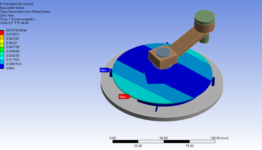
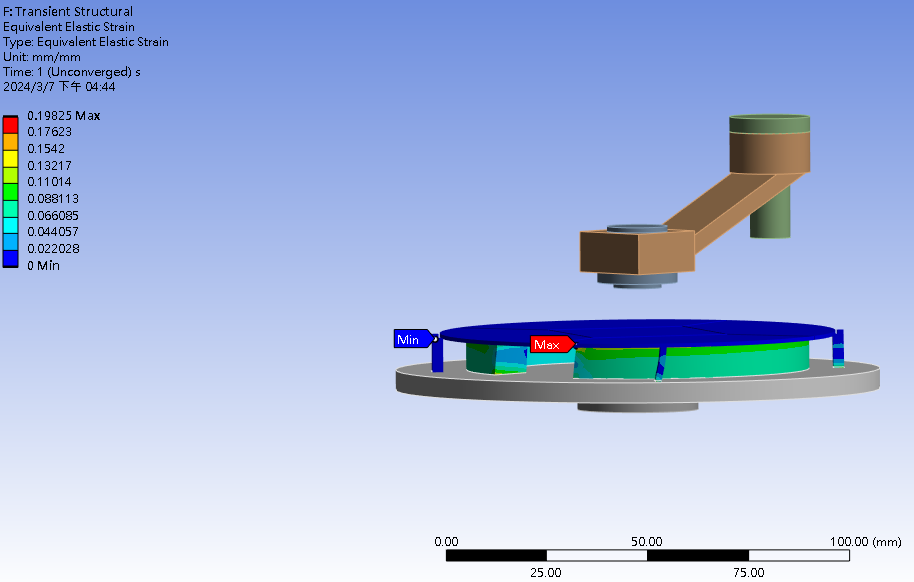
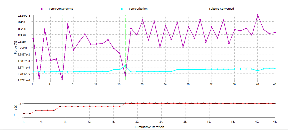
SubscriberHello, thank you for addressing my previous concerns. The mesh for the model seems to have been resolved, but there are still issues with convergence and force conduction.
Below is the message I received after solving in WORKBENCH:
- The solver engine was unable to converge on a solution for the nonlinear problem as constrained. Please refer to the Troubleshooting section of the Help System for more information.
- The solution failed to solve completely at all time points. Restart points are available to continue the analysis.
- Although the solution failed to solve completely at all time points, partial results at some points have been able to be solved. Please refer to the Troubleshooting section in the Help System for more details.
- The unconverged solution (identified as Substep 999999) is output for analysis debug purposes. Results at this time should not be used for any other purpose.
- The work load is highly imbalanced for this Distributed Ansys solution, due to the contact elements in (Tw - L chuck). This will negatively impact the scaling at higher core counts. You may select the offending pair via RMB on this warning in the Messages window.
- One or more MPC contact regions or remote boundary conditions may have conflicts with other applied boundary conditions or other contact or symmetry regions. This may reduce solution accuracy. Tip: You may graphically display FE Connections from the Solution Information Object for non-cyclic analysis. Refer to Troubleshooting in the Help System for more details.
- Two or more remote boundary conditions are sharing a common face, edge, or vertex. This behavior can cause solver overconstraint and is not recommended, please check results carefully. You may select the offending object and/or geometry via RMB on this warning in the Messages window.
- The Combine Restart Files property under Analysis Settings needs to be set to Yes if the core number is modified for a Restart Analysis.

-
March 7, 2024 at 12:48 pm
Ashish Khemka
Forum ModeratorHi, I think it would be difficult to comment without looking at the model. Please wait for other forum members to comment.
Regards,
Ashish Khemka
-
Viewing 3 reply threads
- The topic ‘Frictional vibrations in the wafer surface cleaning process.’ is closed to new replies.
Innovation Space


Trending discussions


Top Contributors


-
4597
-
1495
-
1386
-
1209
-
1021
Top Rated Tags


© 2025 Copyright ANSYS, Inc. All rights reserved.
Ansys does not support the usage of unauthorized Ansys software. Please visit www.ansys.com to obtain an official distribution.


