-
-
May 19, 2023 at 6:48 am
Pranshu Kharbanda
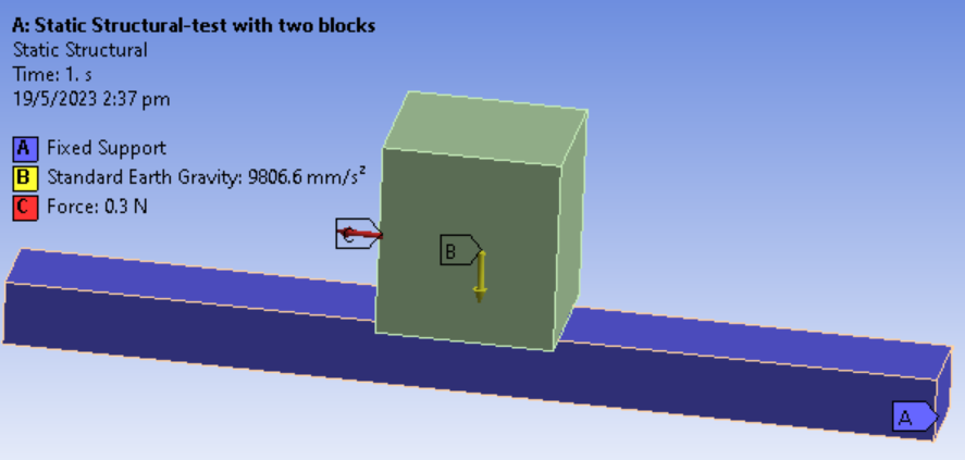
SubscriberTrying to run a simple test to understand frictional contact as shown below, between the two bodies.
Contact initial information is closed as shown, with zero penetration and gap.

I have applied force of 0.3 N here, and according to calcs sliding isn't expected; Fapplied > coeff of friction (0.3)* m(0.1430)*g.
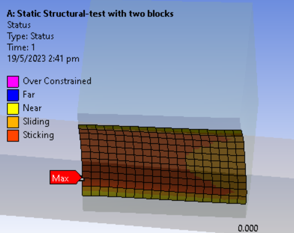
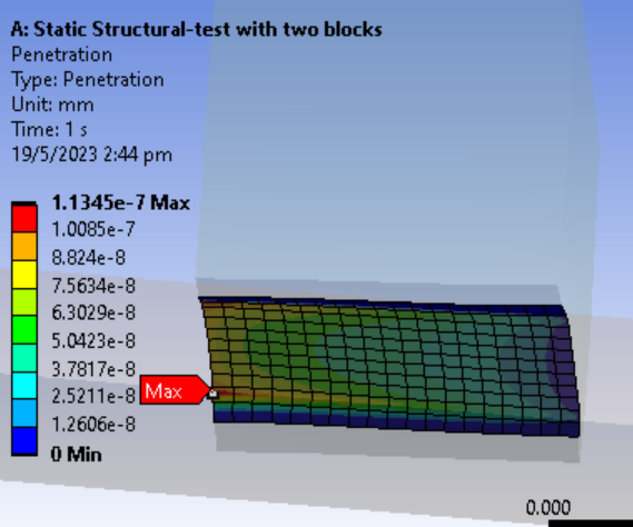
However, when I check the status using contact tool in solution I can see partial sliding as shown allong with penetration. Can I understand why is it so? I have even turned off small sliding from settings. Contact alg is augmented lagrange- program controlled
Thanks
-
May 19, 2023 at 11:27 am
peteroznewman
SubscriberThe contact algorithm uses a tiny amount of penetration in order to calculate the normal force, so this is the expected behavior and the magnitude of the penetration is negligible in this case.
The hand calculation shows the block as a whole does not slide and this is the result that Ansys provides, most of the contact surface is sticking, only a small portion on the right is sliding.
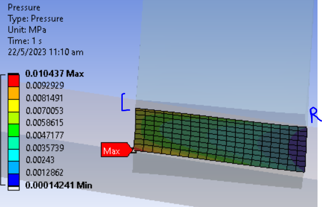
The reason a small portion is sliding is because the normal force is not uniform, it is higher on the left and lower on the right. Plot the Contact Pressure and you will see that. The applied force on the left face combined with the sticking contact elements creates a moment that causes the left side to press down more than the average pressure and the right side to press down with less than the average pressure.
-
May 22, 2023 at 3:23 am
Pranshu Kharbanda
SubscriberHi Peter, thanks for the prompt explanation.
Yes, I can see that the pressure is higher on left. Also the animation shows the moment causing the block to be pressed more on the left.
Can you help clarify a bit more as to what is causing the normal force (due to gravity) to be not uniform ?
Also, I increase the force so that it is greater than frictional force to see sliding behavior (in transient structural, as I understand that static structural is to be used when a=0 or net force is balanced). However, I experience error that abrupt change in contact status. Could it be because of the limited length of the lower long block and the top block flies off ?
-
May 22, 2023 at 10:36 am
peteroznewman
SubscriberFor the Static Structural Analysis
Under Analysis Settings, change the number of Steps to 2.
Edit the Force so that it is 0.0 N in Step 1 and 0.3 N in Step 2.
Solve the model and look at the contact pressure at Time = 1 and you will see that it is uniform along the length of the supporting beam.
The applied Force causes the contact pressure to become non-uniform.
For the Transient Structural Analysis
Is the contact status message a warning or an error? If you use a small enough maximum time step under Analysis Settings, you should be able to see the block break free and accelerate away. It can even leave the end of the supporting bar and begin to free fall.
-
May 23, 2023 at 5:50 am
Pranshu Kharbanda
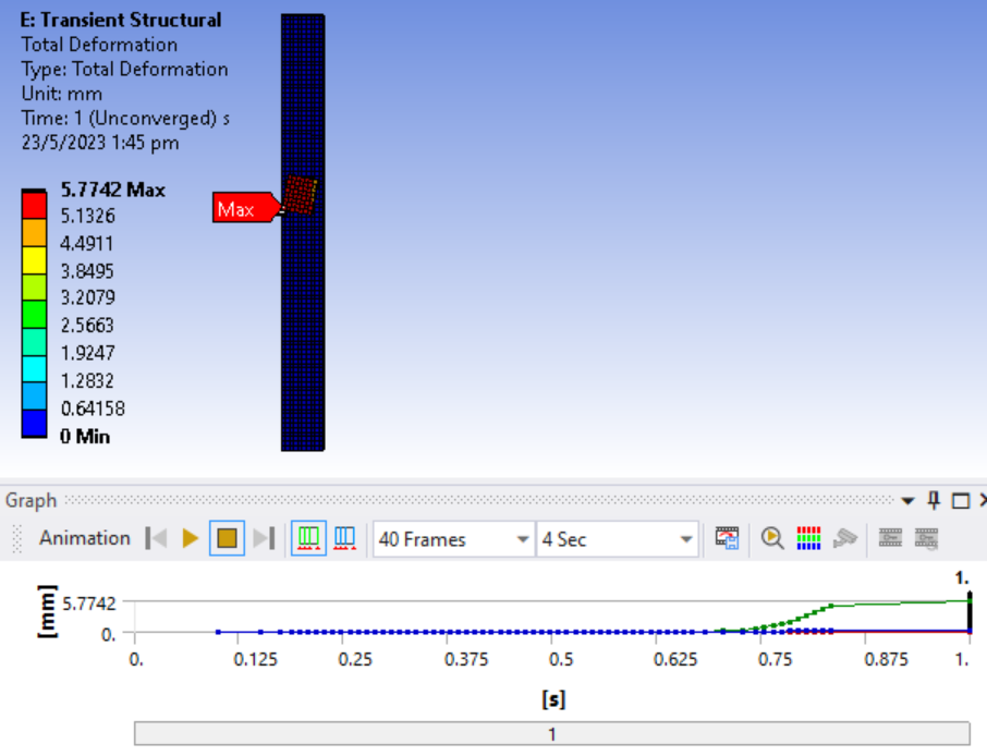
SubscriberYes, I was expecting to see the block breaking free in transient however the solution is unable to converge. Even the block moves 0.6 mm only. I have applied force in steps from 0 to 0.5 N
I tried to reduce the minimum time step to 0.01 s, and the displacement increased to 5.774 . However the solution still couldn't converge.
I am not sure if I am missing something simulating this, as I thought block sliding on surface is relatively simple from physics perspective but the simulation is not converging here. The block is also not moving in a straight line it seems.
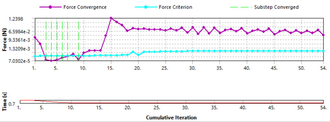
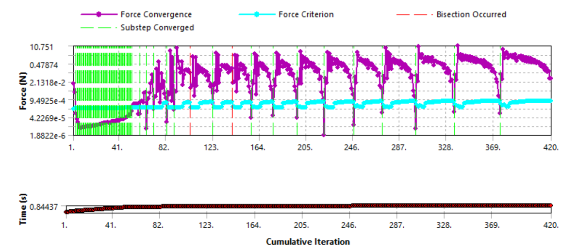
The error and warnings are as below,
-
May 23, 2023 at 3:06 pm
Pranshu Kharbanda
SubscriberOh.. I turned large deflection off and it showed the expected output as you had mentioned . i am unable to upload the animation here
-
-
-
May 23, 2023 at 3:35 pm
peteroznewman
SubscriberIn Transient Structural, leave Large Deflection turned On.
Break the Transient Structural into two steps. Step 1 raises the force to just below the value when the block will break free. Step 1 can have an End Time of 1 s and relatively large Initial and Maximum Time Steps of 0.1 s and a Minimum Time Step of 1e-5 s.
Step 2 has a slightly higher value of force that is above the break free value. Step 2 can have an end time of 1.1 s but it has a small Initial and Maximum Time Step of 1e-3 and a Minimum Time Step of 1e-5 s.
-
May 24, 2023 at 9:44 am
Pranshu Kharbanda
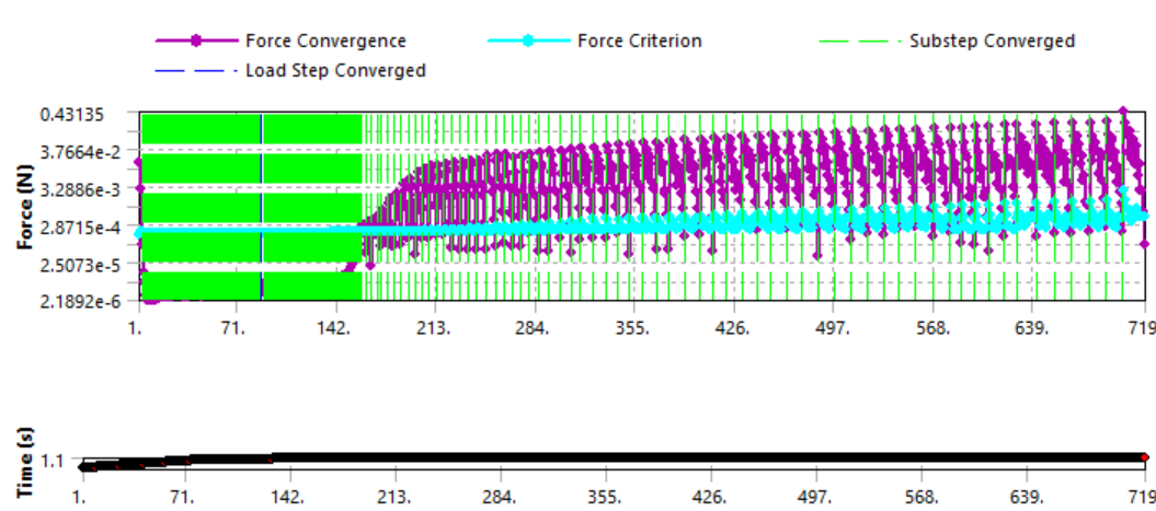
SubscriberThanks for the input. Okay, so I have did that and the solution converged.
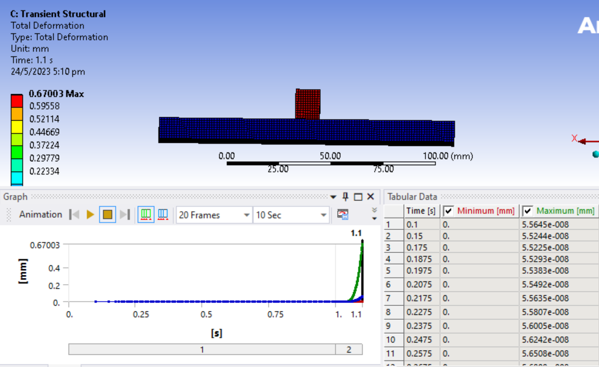
The top block only moves by 0.67 mm max and doesn't fly off. I suppose this is because of the short time duration of 1 to 1.1 s. Is there any way to double check the force at which sliding starts.
Since this simulation takes long time , may I ask if usually we need to specify this small increment of load steps for frictional contact? Is it the sliding behavior that is causing this highly nonlinear phenomenon. As I would have to move on to more complex tasks based on my understanding for this. Thanks again.
-
-
May 24, 2023 at 10:11 am
peteroznewman
SubscriberHighly nonlinear models generally require small time steps. To reduce the elasped computational time you want to reduce the time per iteration and reduce the number of iterations.
Reduce the time per iteration by reducing the number of nodes in the model. Under Mesh, change the Element Order from Program Controlled to Linear. Also reduce the number of elements. The beam on which this block is sliding can be a single element instead of hundreds of elements. That will allow each iteration to compute in a fraction of the time this model currently takes, maybe by a factor of 10 or more.
The other method to reduce the elasped time is to only use small time steps where they are needed. I did that by breaking the model into two steps where step 1 has large time steps and step 2 has small time steps. If you want to see the block slide further, add step 3 and you will be able to increase the time step again, but probably not as large as step 1. You can also try larger maximum time steps in step 2 and see what is needed. I just gave a value I thought would work without testing it first.
-
May 25, 2023 at 7:56 am
Pranshu Kharbanda
SubscriberAh the node reduction helped to reduce time ,thanks much!
Yes, i tried to add more steps and also change the time steps and iterations here, could finally see the block fly off. Will try to work towards modifying the frictional coefficient for the part where it is sticking vs when it starts to slide now.
thank you
-
- The topic ‘Frictional Contact’ is closed to new replies.


-
4823
-
1587
-
1386
-
1242
-
1021

© 2026 Copyright ANSYS, Inc. All rights reserved.

