We have an exciting announcement about badges coming in May 2025. Until then, we will temporarily stop issuing new badges for course completions and certifications. However, all completions will be recorded and fulfilled after May 2025.
Fluids

Fluids

Topics related to Fluent, CFX, Turbogrid and more.

Free Surface with Wave Boundary Condition Incorrect Initialization

    • rnegrete
      Subscriber

      I want to create an open channel with a wave boundary condition in the inlet with Ansys Fluent. Everything seems fine except for a little edge of extra water parallel to the inlet as shown in the picture. Why is this happening? how can it be corrected?
      Thanks

    • Rob
      Forum Moderator

      How many time steps have you run? Ie is this a real result or just an oddity of the initial conditions. What boundaries have you set? 

    • rnegrete
      Subscriber

      I have run several simulations with more than 1000 steps and I find the error every time and it carries on into the simulation making the wave break when it shouldn't. Even after the first wave, the error continues in the subsequent waves.  I have set inlet as velocity-inlet, the top and outlet boundaries as pressure outlets. With and without a numerical beach. The height of the oddity seems to be the same as the wave height for some reason.

      Thanks

    • Rob
      Forum Moderator

      I've not seen that with open channel before, you are using a single boundary surface at each end?

    • rnegrete
      Subscriber

      I'm not sure I understand what you mean but I think there's only one surface per boundary unless "interior" boundary is a second one.

      I made a cube in Design Modeler, marked surfaces as inlet, outlet, top, bottom and walls. It shows 1 Part, 1 Body named Domain. I made a mesh with CFX without changing or renaming boudaries, and then configured on Fluent as follows:

      inlet: velocity-inlet. Open Channel Wave BC ticked, Al defaults in Momentum tab, in Multiphase tab Free Surface=0, Bottom Level=5.6, Fifth Order Stokes Waves, Wave Height=1.73, Wave Length=20. I ran command define, then o-c-w-s and check passed.

      outlet: pressure-outlet, Momentum: defaults, Multiphase Free Surface=0, Bottom Level=5.6.

      top: pressure-outlet, Momentum: defaults, Multiphase Free Surface=0, Bottom Level=5.6.

      walls: wall: defaults

      I also have a bounday "interior-domain" that I didn't create and it's marked as interior.

      Maybe the "interior-domain" could be a second boundary on each surface? How can I remove it if that's the case?

      Thanks

    • Rob
      Forum Moderator

      Interiors are boundaries between cell zones or the facets that make up the volume mesh and should be left alone. There are exceptions, but this isn't one of them. 

      I assume you mean Ansys Meshing and not CFX? Did you set Fluent as the CFD solver at the mesh stage? 

      Bottom is -5.6m? Double check the wave height definition, I can never remember if it's amplitude or displacement from mean. 

    • rnegrete
      Subscriber


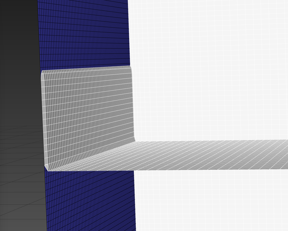
      I’m sorry, it’s the meshing that comes with the Analysis System “Fuid Flow (Fluent)”. I used Physics Preference: CFD, and Solver Preference: Fluent in the mesh stage.

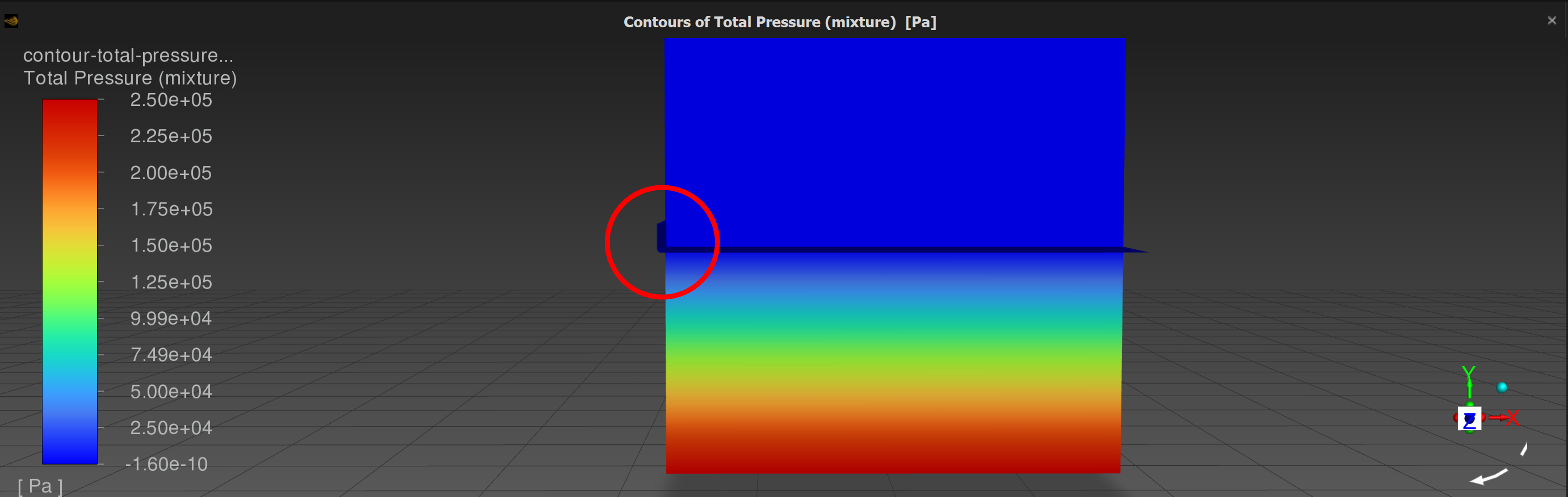
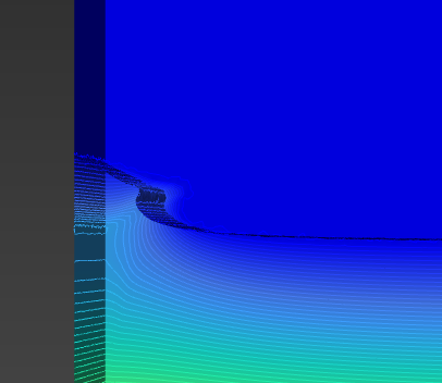
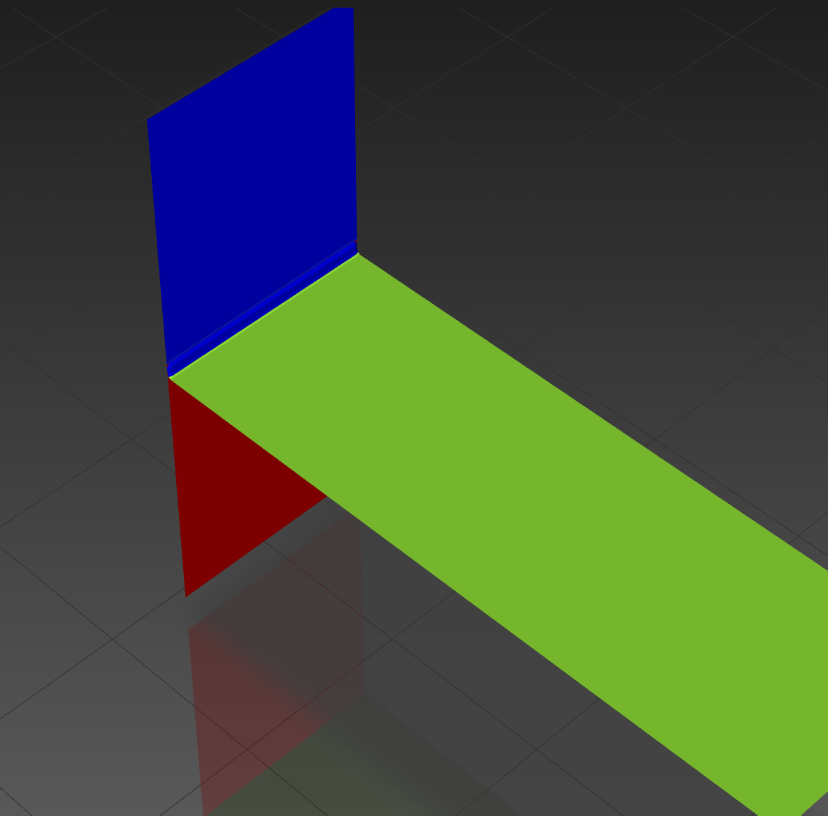
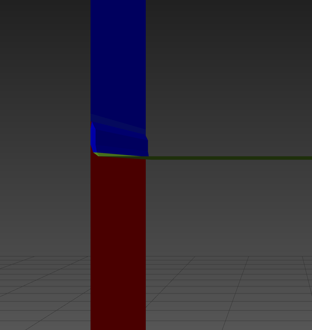
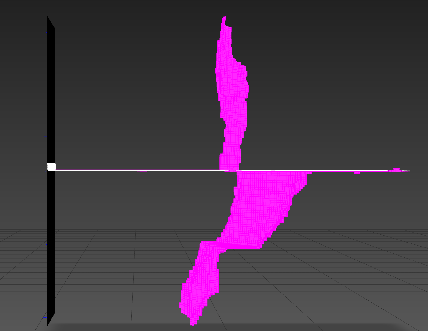
      Bottom level is indeed -5.6 and the free surface is at 0. There are also 5.6 m of air above the free surface and the top of the domain.

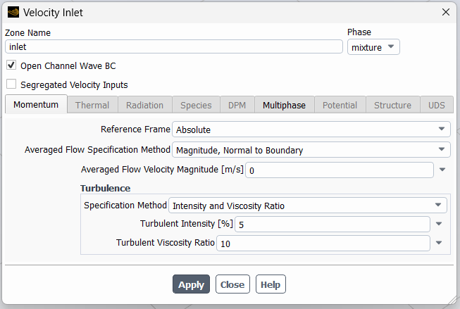
      Here’s the output for define -> b-c -> o-c-w-s

      Wave Input Analysis for Velocity Inlet : Thread ID = 5

      ************************************************************


      Wave-1 Analysis

      *****************************************


      Current Settings :

      ——————

      Wave theory : 5th-order-Stokes , Wave regime = Shallow/Intermediate

      Wave Height (H) = 0.8650, Wave Length (L) = 30.0000

      Liquid Depth (h) = 25.0000, Ursell Number (H*L*L/(h*h*h)) = 0.0498


      Mandatory checks for full wave regime within wave breaking limit

      —————————————————————–

      Relative Height: H/h = 0.0346 , Maximum theoretical limit = 0.7800

      Maximum numerical limit = 0.5500

      Relative height within wave breaking limit


      Wave Steepness: H/L = 0.0288 , Maximum theoretical limit = 0.1420

      Stable numerical limit = 0.1000 , Maximum numerical limit = 0.1200

      Wave steepness within wave breaking limit


      Checks for selected wave theory within wave breaking and stability limit

      —————————————————————————-

      Relative height check

      H/h = 0.0346 , Min : 0.0000 , Max : 0.5000

      Relative height check : successful


      Wave Steepness check

      H/L = 0.0288 , Min : 0.0000 , Max : 0.1420

      Wave steepness check : successful


      Ursell Number check

      Ur = 0.0498 , Min : 0.0000 , Max : 25.0000

      Ursell number check : successful


      Wave regime check

      h/L = 0.8333 , Min : 0.0600 , Max : 10000.0000

      Wave regime check : successful


      Summary

      ———————-

      Checks : passed

      Selected wave theory is appropriate for application.

      Thanks


    • Rob
      Forum Moderator

      Thanks, with all of the products it's difficult to keep track. We used to have CFX Meshing before that became Ansys Meshing after Fluent was bought. So some tools have changed names over the years just to make it really simple..... 

      The wave checks are to ensure the inlet is numerically valid, and won't (usually) mess up the inlet conditions. Can you plot volume fraction on the inlet with node values off? I just want to see if there's anything weird in the contour. Otherwise I'm a little stuck as it's behaving in a test here. 

    • rnegrete
      Subscriber

      Please find the plots below

      Thanks

      and with mesh

    • Rob
      Forum Moderator

      You may benefit from a little more resolution around the free surface but the mesh looks OK. How are you initialising the solution?

    • rnegrete
      Subscriber
      I've tried 3 methods to initialize the solution:
       
      Method 1 - Standard with defaults: I initially computed from inlet and then on the next initializations I've left it blank, Reference Frame: Relative to Cell Zone, Open Channel Initialization Method: Flat, Localized Turbulence Initialization Method: Unticked, Gauge Pressure: 0, X Velocity; 0, Y Velocity; 0, Z Velocity; 0, Turbulent Kinetic Energy: 3.75e-07, Specific Dissipation Rate: 1.047235, Water Volume Fraction: 0.
       
      Method 2 - Hybrid Initialization with defaults: I initially computed from inlet and then on the next initializations I've left it blank, Open Channel Initialization Method: Flat.
       
      Method 3 - Standard Initialization with defaults (as above) and patching the zone with the oddity with air.
       
      In all cases I have the inlet oddity.


      In Models -> Multiphase: 
       
      Models Tab: Model: VOF, Volume Fraction Parameters: Implicit, Body Force Formulation: Implicit Body Force ticked, VOF Sub-Models: Open Channel Flow and Open Channel Wave BC both ticked, Interfase Modeling Sharp.
       
      Phases Tab: Air is Primary Phase and Water Secondary.
       
      Phase Interaction Tab: Force Setup: constant 0.072, Global Options: Surface Tension Modeling ticked, Continuum Surface Force selected, Adhesion Options: Wall Adhesion ticked. (I also tried without surface tension)


      In Solution -> Methods: defaults. Scheme: SIMPLE, Spatial Discretization: Gradient: Least Squares Cell Based, Pressure: PRESTO!, Momentum: Second Order Upwind, Volume Fraction: Compressive, Turbulent Kinetic Energy: Second Order Upwind, Specific Dissipation Rate: Second Order Upwind, Pseudo Time Method: Off, Transient Formulation: First Order Implicit, Non-Iterative Time Advancement unticked, Wrapped-Force Gradient Correction unticked, High Order Term Relaxation unticked.


      Here's an image with a refined inlet mesh.
       
      Thanks!
       
       
    • Rob
      Forum Moderator

      That's odd as it's working in a test I'm running here. 

    • rnegrete
      Subscriber

      It's very wierd indeed. I can't think of anything else to try or where does the oddity comes from... I even tried initialization with Open Channel Initialization Method: None, and patching the water region with water and no joy... Can you think of anything else that could be causing it?

      Thanks

    • Rob
      Forum Moderator

      Not sure, and I'm not able to download anything to test on this side to be able to test. 

    • Amine Ben Hadj Ali
      Ansys Employee

      What are your BC's? Is that bump at inlet or at outlet? Did you initialize with "wave" option on or not?  Disable surface tension. 

      Provide the screenshot of the BC where the wave is entering to check wave settings.

    • rnegrete
      Subscriber


      BCs: 

      inlet: velocity-inlet. Open Channel Wave BC ticked, Al defaults in Momentum tab, in Multiphase tab Free Surface=0, Bottom Level=-5.6, Fifth Order Stokes Waves, Wave Height=1.73, Wave Length=20. I ran command define, then o-c-w-s and check passed.

      outlet: pressure-outlet, Momentum: defaults, Multiphase Free Surface=0, Bottom Level=5.6.

      top: pressure-outlet, Momentum: defaults, Multiphase Free Surface=0, Bottom Level=5.6.

      walls: wall: defaults

      bottom: wall: defaults


      The bump is in the wave velocity inlet


      I did initialize with wave option and the oddity is not visible on the first step but when the wave starts to come in, there's a signifficant change in the slope of the wave giving a similar result during simulation, furthermore, it happens in every wave, not only on the first one.


      I tried with and without surface tension.


      All the screenshots are from the velocity inlet from where the wave is entering the domain. 

      Thanks!


    • Amine Ben Hadj Ali
      Ansys Employee

      One needs to reproduce this on our side that we understand what is going on so please provide some more context on the domain extents. A 2D abraction of the case can aslo help to understand if this due to the wave module or more or less issue with the lack of resolution of the wave (at least 20 cells per height / 200 cells per wavelength, at least 2X Wave Length above the free surface domain height) or a completely different issue.

    • rnegrete
      Subscriber

      The wave seems fine after changing the domain to the specifications above.

      Thank you very much!!

    • Amine Ben Hadj Ali
      Ansys Employee

      Welcome and Good Luck with the next steps!

Viewing 18 reply threads
  • The topic ‘Free Surface with Wave Boundary Condition Incorrect Initialization’ is closed to new replies.