-
-
October 19, 2023 at 1:09 pm
KANTUBHUKTA HEMANTH HARI KISHORE
SubscriberGreetings to everyone,
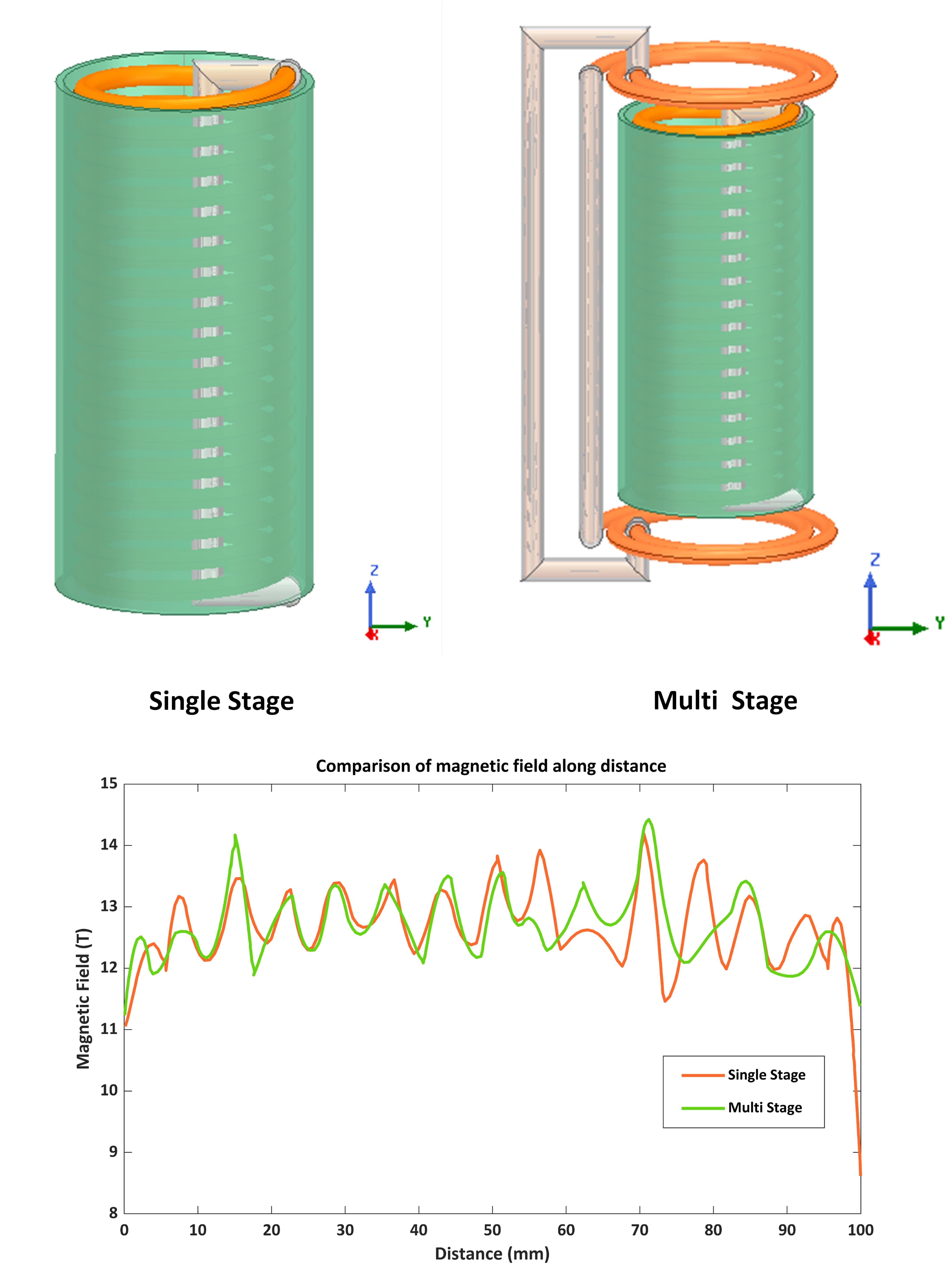
I'm Hari Kishore. I'm doing Transient analysis, for a tube(100mm length) and a coil placed inside the tube, in ANSYS Maxwell. There are two such models are shown, viz.
- Single Stage - tube and middle coil.
- Multi Stage - tube, middle coil, and two end coils(connected in series).
For the excitation of coils, I've used a current dataset obtained from an experimental set up.
The magnetic field along the inner surface of the tube (i.e., along distance at a particular time) is unsymmetric even though my modal is symmetric. I've shown the magnetic field distribution for both models.
Why is it unsymmetric? I want to get a peak at the center and symmetrically reducing curve to either side.
Could you please assist me in getting a symmetric curve?
-
October 20, 2023 at 10:59 am
-
October 22, 2023 at 5:03 am
-
October 23, 2023 at 6:05 pm
Reshmi Raghavan
Ansys EmployeeHello Hari,
I believe the line is drawn along Z direction on the inner surface of the tube. As per the field plots you can find that the B field will be high towards the center of the tube height and depending on the coils turns the ups and dips would be formed. The field quantity always takes up the shortest reluctance path and at the corners the field will be minimum compared to the center of the tube in Z direction.
-
October 24, 2023 at 9:17 am
KANTUBHUKTA HEMANTH HARI KISHORE
SubscriberHello Reshmi Raghavan,
Thank you for yor great response. Yes! I've drawn the line along inner surface of tube. I understood that the geometry of coil, make the magnetic field curve to have ups and dips. Since, B field is high towards center, I should get a curve which has peak at center and reduce towards ends of tube, insetad peak occurs somewhere. And also the curve must be symmetric from center, instead I'm getting unsymmetric. Is it because of geometry or something else i.e., effecting the symmetriness?
I want to get a symmetric magnetic field.
Thank you.
-
November 3, 2023 at 3:59 am
Reshmi Raghavan
Ansys EmployeeHello Hari,
Few points that could result in this sort of ditorted waveform are as below.
1) geometry - the coils are helical in nature with air gaps between them and a current carrying coil passing through the cneter of the coil too. This would cause ups and dips in the waveform and non uniformity in the waveform.
2) Mesh- meshing too has to be refined to capture the field behaviour.
-
- The topic ‘For a symmetric modal not getting symmetric magnetic field’ is closed to new replies.


-
4878
-
1587
-
1386
-
1242
-
1021

© 2026 Copyright ANSYS, Inc. All rights reserved.


