-
-
January 8, 2024 at 6:29 pm
Maryam Tabbakhh
SubscriberHi,
I was trying to put an scale factor on my model but the movement of fluid in x direction is not showed. In my model fluid is inside the tank. When I apply the scale factor in the whole model in x,y and z direction, the motion of tank increased in x direction (the direction of applying load) and fluid is sloshing inside the tank. But when I apply the scale factor I can't see the amplification factor in fluid which is sloshing in the tank. Can you please help me how to show it?
Best
Maryam
-
January 9, 2024 at 3:34 pm
Federico
Ansys EmployeeHello Maryam,
can you provide some screenshots showing this issue?
-
January 10, 2024 at 6:52 am
Ushnish Basu
Ansys EmployeeWould it help to display only the fluid part and then apply the scale factor?
-
January 10, 2024 at 5:30 pm
-
January 10, 2024 at 7:45 pm
Maryam Tabbakhh
SubscriberI have one more question. How can I find the elevation of water at different points? It doesn't show with nodeout.
-
January 15, 2024 at 10:04 pm
Ushnish Basu
Ansys EmployeeAre you solving an ALE problem? In that case, I will ask our ALE exper to chime in
-
January 16, 2024 at 4:50 pm
Maryam Tabbakhh
SubscriberYes. I am working on ALE and appreciate a lot if you refer me to someone to help me with this.
-
January 17, 2024 at 6:45 pm
Ian Do
Ansys EmployeeHello Maryam,
Please try:
- define some dummy nodes (free floating) via *NODE for the location of the tracers at t=0.0
- define *DATABASE_TRACER (simplest) using these dummy nodes as starting locations for the tracers. Distribute the tracers on the top of the liquid/fluid, but slightly inside the fluid - and point to that fluid's AMMGID so that the tracers will follow that fluid.
Some of the tracers may wander off the surface positions due to local numerical inaccuracy. It is expected. Finer resolution will give better accuracy n tracking.
Hope this helps.
Ian Do
-
January 17, 2024 at 6:50 pm
Ian Do
Ansys EmployeeAnd use LAGRANGIAN tracers or "particle follows material" to allow the tracers to follow the fluid, TRACK=0.
-
January 17, 2024 at 6:59 pm
Maryam Tabbakhh
SubscriberHi Ion,
thank you so much for your response:
couple of questions. So should I define new nodes at the surface of water or I can pick some nodes from my model just right at the water surface?
how can I see results? In ascii? And what item should I look for?
best
-
January 17, 2024 at 7:36 pm
Ian Do
Ansys EmployeeHello Maryam,
[1] dummy floating nodes ==> you can visualize the positions of these nodes by ELEMENT==> FIND ===> NODES ==> enter these NIDs ==> display them ==> animate
[2] In LSPREPOST
Load up d3plot
load binout
load trhist
select tracer ID
you can then plot their coor. or vel, etc.
Ian
-
January 17, 2024 at 7:37 pm
Maryam Tabbakhh
SubscriberGreat! Thanks so much
-
January 18, 2024 at 12:34 am
Maryam Tabbakhh
SubscriberHi Ian,
I picked some nodes from the model as shown in the picture, actually I found the nodes location from the model and they are real nodes. Then I added :
*DATABASE_TRACER
$# time track x y z ammgid nid radius
0.0 0 0.0 0.0 0.0 2 17408 0.0but the analysis does not converge. Without the tracer it is converged.
what is the solution? I think I made something wrong.
-
January 18, 2024 at 12:50 am
Ian Do
Ansys EmployeeMaryam,
The nodes used for locating the tracers must be floating dummy nodes. They cannot be ALE mesh nodes (those are fixed to the mesh and cannot move with the mats).
Ian
-
January 18, 2024 at 1:19 am
Maryam Tabbakhh
SubscriberIan,
how can I generate floating dummy node? So for example I got the coordination of node 17408 and added a node to the system with the same coordinate. Is this the right way?
-
January 18, 2024 at 3:26 am
Ian Do
Ansys EmployeeSlow down in your reading ;-) ! I mentioned it the first thing you do before :
Please try:
- define some dummy nodes (free floating) via *NODE for the location of the tracers at t=0.0
-
January 30, 2024 at 11:07 pm
Maryam Tabbakhh
Subscriberthank you so much. It did work!
-
March 8, 2024 at 11:55 pm
Maryam Tabbakhh
SubscriberHi,
I still have a problem with applying scale factor to the fluid. we wanted to check if the fluid works properly and needed to exagerate the fluid displacement in the animation. When I apply scale factor to the displacement for the fluid, the whole fluid jumps out but the deformed shape is still the same. The wave height doesn't change. Is there anyway that I can see the amplified motion through the displacement scale factor or anything else? I tried the lsprepost4.11 and still the same problem.
Thank you so much
-
March 14, 2024 at 5:04 pm
Ian Do
Ansys EmployeeHi Maryam,
Your description is not clear.
Pls show the exact sequence you executed in LSPP or some pics.
-
March 14, 2024 at 7:42 pm
Maryam Tabbakhh
SubscriberHi Ido,
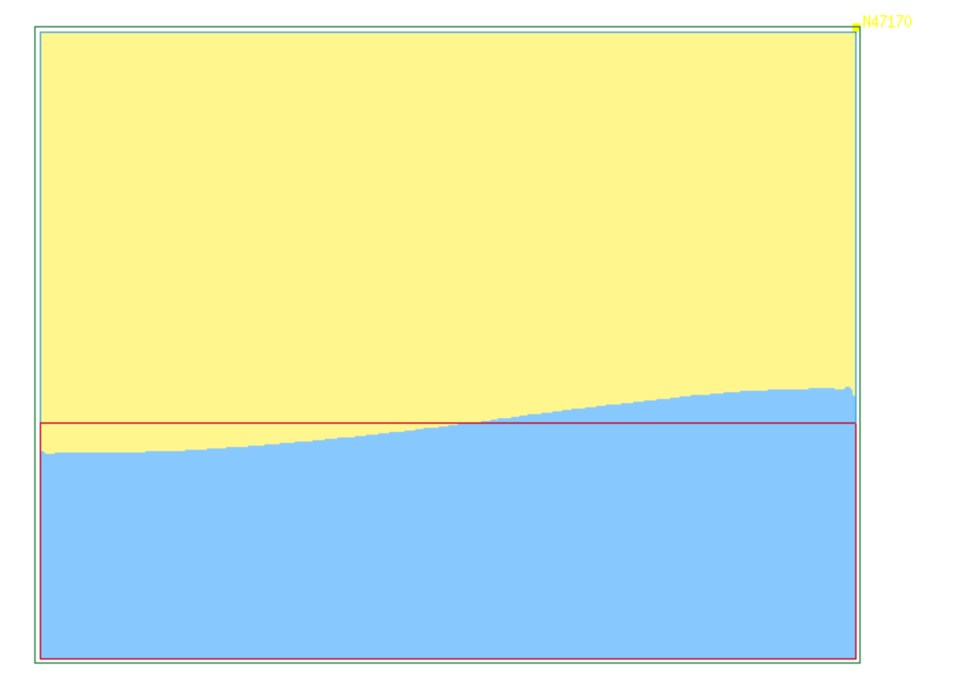
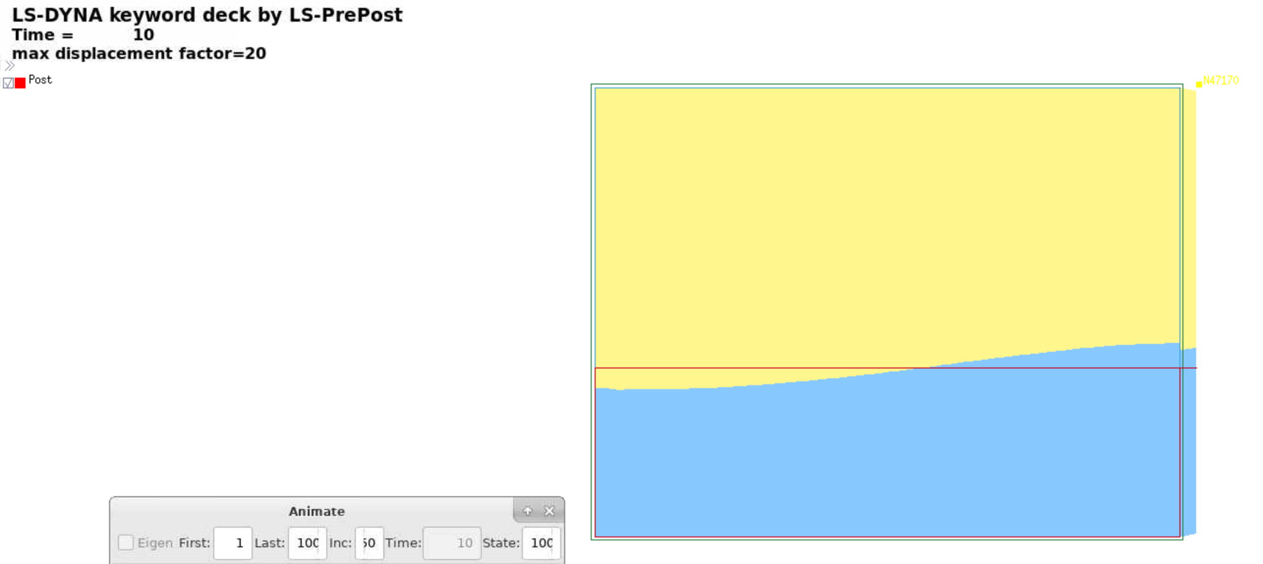
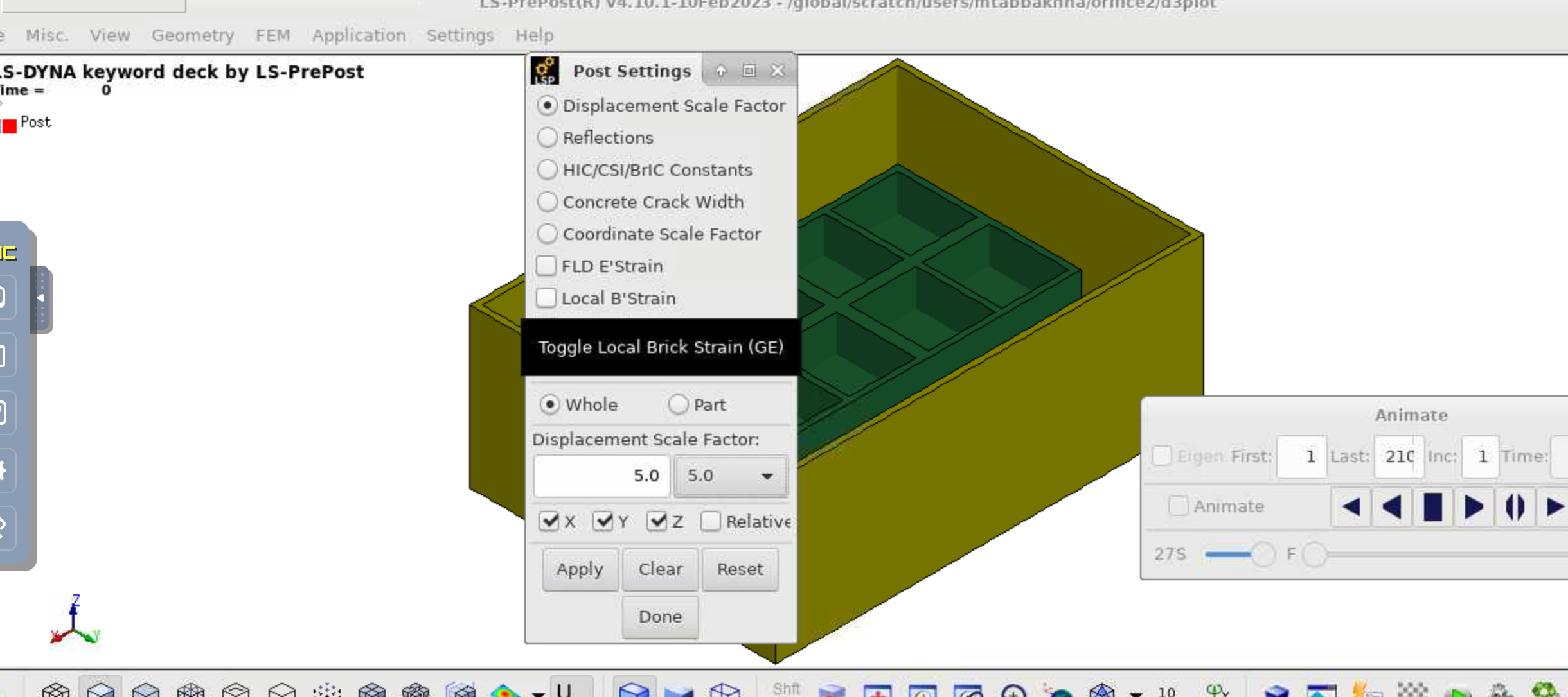
Sure. I have a block sink in the water, I first apply gravity on it and then apply earthquake motion to the tank. We want to see what is the response of fluid under earthquake loads. So when the analysis is done, I just pick my block first, go to post setting apply scale factor of 5 to see what is the displacement of the block. We do amplification to make sure there is no torsion in my block. One way to check our model is applying displacement scale factor to see how does the animation look like. We want to do the same thing with the fluid in the tank. I turn on fluid part (ALE water) and want to see
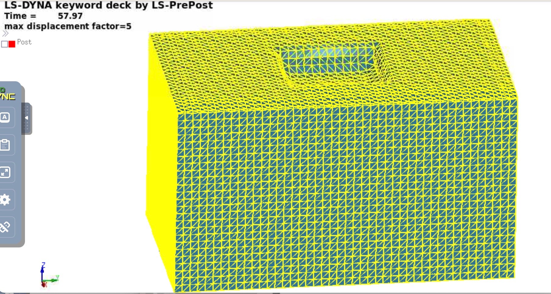 what is the response of water. when the scale factor is 1 everything looks correct. We want to apply amplification factor of 3 to the ALE part to see how is the amplified version of the fluid displacement look like. But when I go to post setting and apply scale factor 3 to displacement, the whole part just jump in horizontal direction and the surface of the water doesn't change. I make a screenshot and send it to you to see how does it look like. the scale factor 1 and scale factor 5 are basically the same. But when I apply displacement scale factor to the structural elements, it will really amplified the displacement 5 times (whatever I want) and I can see real changes. I wanted to see if there is anyway that I amplify displacement or deformed shape of fluid? Please let me know if you need more information,
 best
Maryam
-
March 15, 2024 at 9:55 pm
Ian Do
Ansys Employeehow do you "apply amplification factor of 3 to the ALE part" ? can you please show the sequence of clicks in LSPP window? (The operation that you want to apply to the ALE mat may not be applicable to the AMMG?)
-
March 15, 2024 at 9:57 pm
Maryam Tabbakhh
SubscriberI can't apply amplification factor 3 to ALE part. I am wondering if I can do that or not or how can I apply amplification factor to ALE part. I just apply Scale factor to displacement in lagrangian part.
-
March 15, 2024 at 11:24 pm
Ian Do
Ansys EmployeeOne more time, can you please show the sequence of "how" you execute this action in LSPP window? i need to duplicate the steps here to see if there is a problem.
-
March 29, 2024 at 7:35 pm
-
April 3, 2024 at 4:02 pm
Ian Do
Ansys EmployeeHi Maryam,
I do not think we can do what you want for for ALE fluid interface displacement. This LSPP feature may be applicable to LAG solid only, where the nodes are attached to the materials. For ALE, the mats flow through the mesh. Not the same concept. We cannot amplify fluid interface displacement, I don't think.
Ian
-
April 17, 2024 at 5:59 pm
Maryam Tabbakhh
SubscriberDear ido and Ushnish,
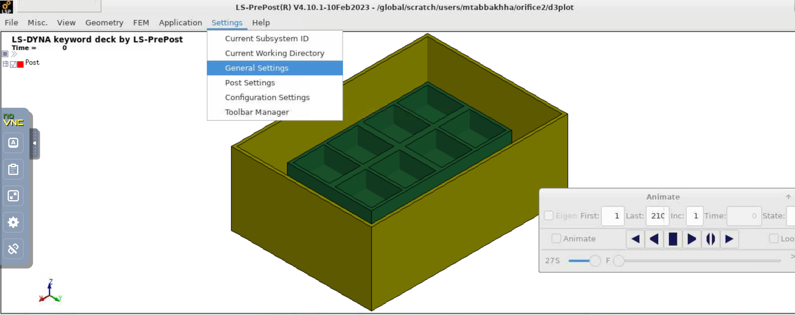
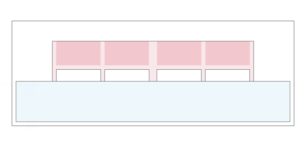
I have an important question about this topic. I want to apply the earthquake in z direction to the tank fill of water with the box floating on it like top figure. I add one more picture to show it better here. I need to first gravity initialize the box and after it reached equilibrium, I am going to apply earthquake just in Z direction. It is basically two step. Step one, from 0 to 5 second, I just apply graviry through a inclined curve and then apply earquake at 5 second ( the acceleration that I provided starts after 5 second). My problem is that I need the base of the tank to be fixed in z direction in order to gravity initiation, but for the next step that I want to apply acceleration in z direction, I need that DOF in z direction to be free. If I fix DOF in z direction, my tank doesn't more in z direction when earthquake applies but the first step (gravity initialization) reaches equilibrium and the problem with having the DOF in z direction free, it doesn't converge in the gravity initialization and box starts to rotate. Do you have any solution for me? I did the same thing for Y direction and the results were successful because for applying earthquake in y direction, I don't need to free the DOF in z direction free and I could get reasonable response. Appreciate any suggestions.
Thanks a lot
Maryam
-
- The topic ‘fluid model displacement factor’ is closed to new replies.


-
4778
-
1565
-
1386
-
1242
-
1021

© 2026 Copyright ANSYS, Inc. All rights reserved.

