-
-
November 2, 2018 at 3:59 am
-
November 2, 2018 at 6:13 am
Amine Ben Hadj Ali
Ansys EmployeePlease add more details about the deployed boundaries (not only inlet) and post a screenshot of the mesh in the inlet region. -
November 2, 2018 at 6:16 am
Keyur Kanade
Ansys EmployeeIs this solution converged?
I assume you are using velocity inlet and pressure outlet.
Once flow is converged, the contours look correct. The flow will not in the direction as you showed it in red line. The flow is driven by pressure difference and as solution progresses, it will aligned to x direction as we have planar pressure outlet on right hand side.Â
Â
-
November 5, 2018 at 12:42 am
-
November 5, 2018 at 12:43 am
rumth
SubscriberHi,
My solution is converged.
My outlet is not in right hand side direction. Please see the image.
-
November 5, 2018 at 6:59 am
Amine Ben Hadj Ali
Ansys EmployeeMesh resolution is poor. Please add some more information about velocity vectors and the location of the outlet. Please tell us whether you have reversal flow or not.Â
-
November 5, 2018 at 12:02 pm
rumth
SubscriberHi,
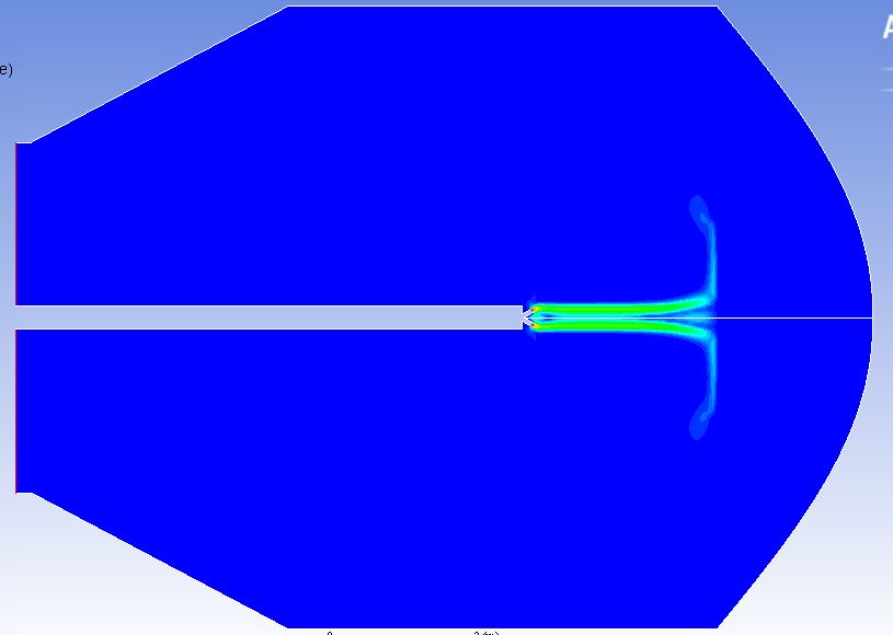
My outlet is at left hand side (you can easily find from the above image). Yes, I have back flow.
As I have run the simulation for small time, there is no remarkable velocity vector. Only velocity vector gives flow direction we can see from the image.
I used the same operating conditions in a rectangular geometry where I got the expected fluid flow pattern. But in this geometry, I am not getting.
-
November 5, 2018 at 12:23 pm
Amine Ben Hadj Ali
Ansys EmployeeThe flow will be-oriented due to pressure gradients. you can check the pressure contours to identify zones of large / small pressures. You have now another flow configuration so no need to compare apples with oranges but enhance your mesh resolution, assess for good initialization and run till the whole flow develop itself.Â
-
- The topic ‘Fluid Flow Direction’ is closed to new replies.
-
4693
-
1565
-
1386
-
1242
-
1021
© 2025 Copyright ANSYS, Inc. All rights reserved.


