-
-
November 26, 2020 at 7:32 am
NatKoba
SubscriberHi Everyone
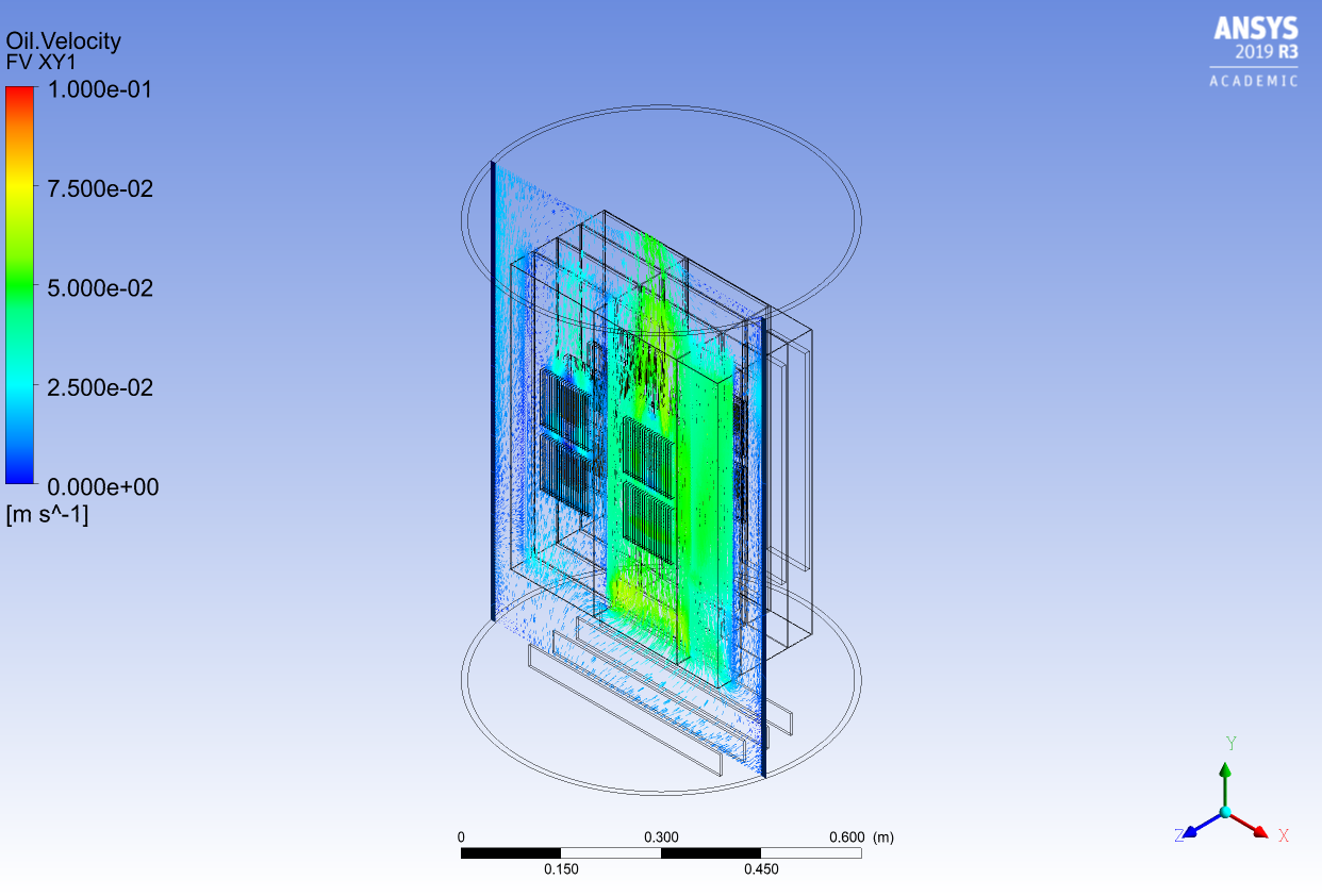
I am currently simulating the effect of bubble in liquid immersion cooling. My cooling tank consists of 16 CPUs and 16 heat sinks and cold plate (surrounding the tank) and it is filled with viscous fluid. Air is injected from the bottom of the tank.
I was able to demonstrate the circular convection of fluid and upward flow of Air. When air flow rate is increased, it is expected to help the heat transfer from heat sink to the fluid and thus it cools the CPUs.
However, no matter how much air I increased, air volume fraction near heat sinks reminds around 1%. I even increased it from 1.0 g/s to 10.0 but with no difference in fraction. Which means no increase in cooling efficiency.
Reading the manual and trying out different parameters haven't solve this problem. Please kindly point me to the right direction, possibly a section in the manual or a tutorial video.
November 26, 2020 at 11:55 amRob
Forum ModeratorWhy would the air move through/around the heat sink and not divert around the outside of the congested regions? What does the air volume fraction contour look like? nNovember 26, 2020 at 3:22 pmAmine Ben Hadj Ali
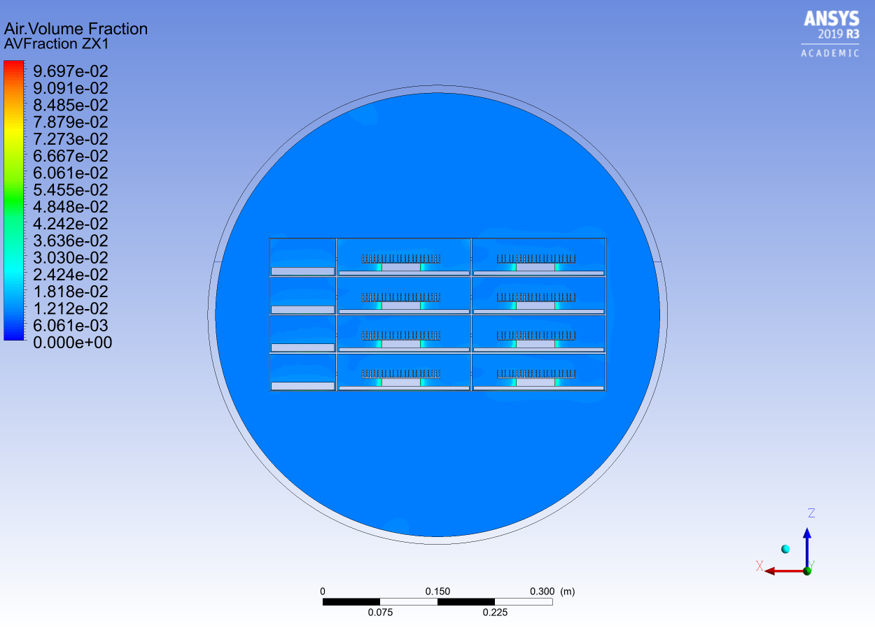
Ansys Employee(Turbulent Dispersion Force + Sato Enhanced Viscosity) both turned on will massively impact the flow behavior of the air bubbles. But if this enough to push the bubbles towards the heat sources: I am not sure. Are you repeating a paper or experiment? How do you know about the bubble size?.As mentioned: VOF Volume Fraction is required to understand but we cannot do much here.nDecember 1, 2020 at 2:55 amSubscriberDear nThank you so very for your quick reply. nWe believe the chassis surrounding CPUs and heatsinks should navigate the air to move through the congested regions. nFollowing your message, I checked the contour of air volume fraction for the 1st time... nAnd it looks like air does move around heatsinks and air faction exceeds 30 % which totally contradicts with my previous results obtained by simply creating a point near neat heatsink and setting a probe under expressions.nAttached, please see the bottom image for the top contour located in the middle of upper heatsinks. nPlease kindly let me know how I should reason this contradiction and how to fix it. n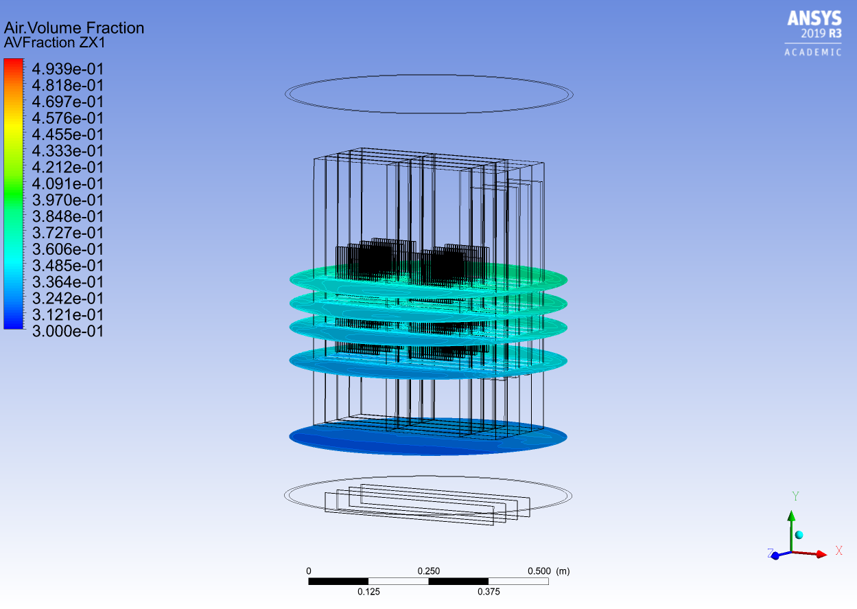
 nBest Regards,nNatn
December 1, 2020 at 8:00 amAnsys EmployeeYou were looking into a point and you were not lucky in the selection of that points. You better check the area average of VOF at the walls or check on several points / planes at different levels.nDecember 3, 2020 at 3:52 amSubscriberDear nThank you for getting back to me. nI actually have 20 points @ various locations near heat sinks as well as inlet and outlet. nAnd all those 22 points have somewhat similar air volume fraction : 1.0~1.5 %. nHowever according to the contour, even between the fins of heat sinks, air volume fraction seems to exceed 30%.nnCloud you please elaborate on 'check the area average of Volume of Fluid at the walls'?nWhich walls are you talking about; heatsink, cold plate or outer layer of cooling tank?nAnd what am I supposed to look for?.Kind regards,nNatnDecember 3, 2020 at 9:03 amAnsys EmployeeYou are seeing where the volume fraction is reaching the higher values. You can monitor all walls and then decide which one to rely on! Also show the volume fraction plot on each of the walls you listed.nDecember 4, 2020 at 12:24 amSubscriberDear nContinuing with the simulation, I no longer get the contradicting results but the original problem reminds. nAttached, please find the air volume fraction contour for air flow rate of 0.3 g/s and 5.0 g/s.nRegardless of the air volume, the results are almost the same (CPU temperature and fluid velocity too). nDoes that mean, 5.0g/s of bubbles is still not enough to make any difference?.I am trying to demonstrate that addition of bubbles increases the cooling capacity. nAnd also I aiming to determine the optimal air diameter and air flow rate.Your insightful feedback would be highly appreciated.Best regards,nNatn
nBest Regards,nNatn
December 1, 2020 at 8:00 amAnsys EmployeeYou were looking into a point and you were not lucky in the selection of that points. You better check the area average of VOF at the walls or check on several points / planes at different levels.nDecember 3, 2020 at 3:52 amSubscriberDear nThank you for getting back to me. nI actually have 20 points @ various locations near heat sinks as well as inlet and outlet. nAnd all those 22 points have somewhat similar air volume fraction : 1.0~1.5 %. nHowever according to the contour, even between the fins of heat sinks, air volume fraction seems to exceed 30%.nnCloud you please elaborate on 'check the area average of Volume of Fluid at the walls'?nWhich walls are you talking about; heatsink, cold plate or outer layer of cooling tank?nAnd what am I supposed to look for?.Kind regards,nNatnDecember 3, 2020 at 9:03 amAnsys EmployeeYou are seeing where the volume fraction is reaching the higher values. You can monitor all walls and then decide which one to rely on! Also show the volume fraction plot on each of the walls you listed.nDecember 4, 2020 at 12:24 amSubscriberDear nContinuing with the simulation, I no longer get the contradicting results but the original problem reminds. nAttached, please find the air volume fraction contour for air flow rate of 0.3 g/s and 5.0 g/s.nRegardless of the air volume, the results are almost the same (CPU temperature and fluid velocity too). nDoes that mean, 5.0g/s of bubbles is still not enough to make any difference?.I am trying to demonstrate that addition of bubbles increases the cooling capacity. nAnd also I aiming to determine the optimal air diameter and air flow rate.Your insightful feedback would be highly appreciated.Best regards,nNatn
 n
Viewing 7 reply threads
n
Viewing 7 reply threads- The topic ‘Fluid Flow (CFX) : problem with Air Volume Fraction’ is closed to new replies.
Innovation Space Trending discussions
 Top Contributors
-
peteroznewman
 5149
5149 -
scabo
 1831
1831 -
Dennis Chen
 1387
1387 -
javat33489
 1248
1248 -
Shyam Prasad V Atri
1021
Top Rated Tags
© 2026 Copyright ANSYS, Inc. All rights reserved.
Ansys does not support the usage of unauthorized Ansys software. Please visit www.ansys.com to obtain an official distribution.
-
Ansys Assistant will be unavailable on the Learning Forum starting January 30. An upgraded version is coming soon. We apologize for any inconvenience and appreciate your patience. Stay tuned for updates.