-
-
February 10, 2022 at 8:29 am
HPatil
SubscriberHello everyone,
I'm an ANSYS beginner and I'm trying to do a project about the heat transfer enhancement due to vortex generators on a turbine blade. In its most basic sense, it is a conjugate heat transfer problem where a high-velocity fluid is transferring its heat to a solid rotor blade. And the objective is to reduce this heat transfer to the blade (because that will increase its temperature).
The approach I intend to take is that, if lesser heat is transferred to the blade, that means more of it is taken away by the fluid after passing over the blade (You are welcome to suggest a better approach! :) ).
So now, coming to the simulation, I created the solid rotor, the enclosure, and created the Fluid cavity with Boolean Subtract (in DesignModeler). Here's the mesh (shown in the XZ plane), it is more dense at the site of the vortex generator due to inflation control.
February 10, 2022 at 11:25 amRob
Forum ModeratorI'm slightly confused as to what you're actually modelling. Turbine blades tend to spin, so "y" isn't overly useful. If the whole lot is rotating you can use sliding mesh, but you also need the fluid region around the blade and up & downstream.
The cell quality is poor, but you may get away with it if those cells aren't anywhere near any significant flow gradients. If they are convergence and accuracy will be less than ideal but the solver should still run.
February 10, 2022 at 4:02 pmHPatil
Subscriber
Well, I know the blades rotate, but I'm considering a very very small time Δt (the time step I've given here is 8e-5 sec), in which they can be approximated to travel with a near linear velocity.
Also, I forgot to mention a very important boundary condition, the temperature of the steam is 300 degrees Celsius, while the blade is at room temperature. So, the high-velocity high-temperature fluid is transferring its heat to the moving blade.
Coming to the 2nd part of your response, the densest part of the meshing (where the vortex generator is attached (not visible in this image coz they're hardly 2% of the entire blade area)) is very much near the flow of interest , so if you're saying that's poor too, that's another issue I'll have to think about. The rest of the blade, not so much.
But the main concern I'm trying to solve here is why isn't the fluid cavity moving with the blade (which is part of a coupled mesh interface), despite adding a moving wall condition to it?
February 10, 2022 at 4:09 pmRob
Forum ModeratorAt the moment I'm struggling to see where the fluid zone around the blade is, and therefore which bits are moving relative to the rest of the domain. Please can you post some images of the geometry?
February 10, 2022 at 4:22 pmHPatil
SubscriberDear Rob, Thank you for replying swiftly.
Well, I know the blades rotate, but I've considered a very very small time Δt (the time step for this transient solution is 8e-5 sec), so in this very small time, it can be approximated to have a near linear velocity. Also, I forgot to mention a very important boundary condition, the steam is at 300 degrees Celsius, while the blade is at room temperature. Apologies to have missed mentioning these key details.
So, the objective is to reduce the heat transferred to the blade, or to enhance the heat carried away by the fluid even after passing over the blade.
Coming to the 2nd part of your response, the densest part of the meshing is where the vortex generators (I'll call them VGs from henceforth) are attached. They're not visible in this image because it's hardly 2% of the entire blade area. So that part is very much near the flow of interest; the rest of the blade... not so much.
However, my main area of concern is that the fluid cavity isn't moving with the blade even after applying a moving wall condition to it. The solution is converging and I got some results too, but clearly they can't be trusted because of the poor mesh quality, and most importantly, the fluid cavity not moving with the solid domain (again, the blade velocity is input under mesh motion).
P.S. the above problem has been detected after the flow convergence calculation itself, the energy equation hasn't been turned on yet (there's an interesting problem happening there as well, but I'll discuss that later... I would like to resolve this stationary fluid cavity problem first.)
Regards
February 12, 2022 at 6:39 pmHPatil
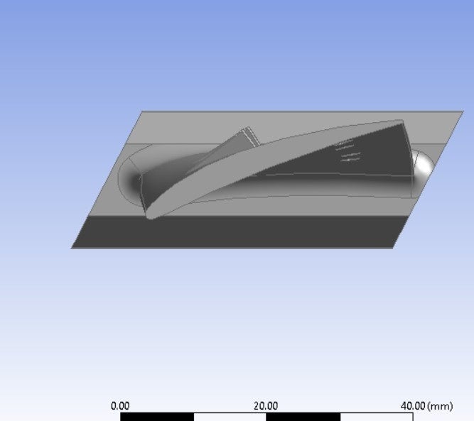
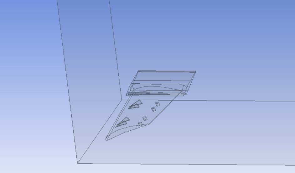
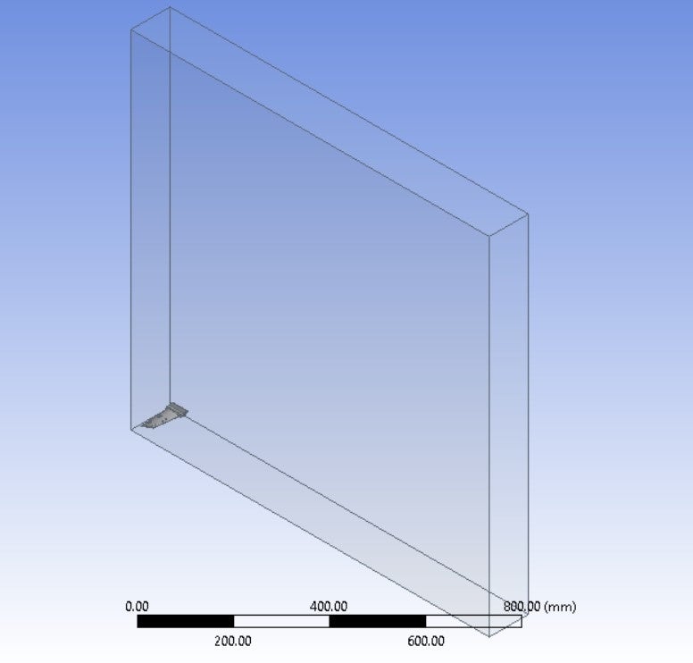
SubscriberSorry for the delayed reply. For viewing purposes, I have enlarged the geometry of interest (VGs) by many times.
This is the blade with attached VGs


And this is the fluid cavity that I'm expecting should move with the blade.
 The entire geometry (fluid enclosure + solid blade is as below
 Hope this helps
February 14, 2022 at 12:13 pm
Hope this helps
February 14, 2022 at 12:13 pmRob
Forum ModeratorAs I can't see any zone around the blade, where is the remeshing/moving zone? I'd expect a section in the outer domain to move with the blade so you could use layering.
February 14, 2022 at 12:28 pmHPatil
SubscriberI don't know what you mean. The fluid cavity in image no.3 is what I am expecting to be moving with the blade. Is that the same thing you're talking about?
February 14, 2022 at 3:04 pmRob
Forum ModeratorIs the whole cuboid moving?
February 14, 2022 at 3:21 pmHPatil
Subscriberno no. that is the stationary enclosure. Just the blade is moving within its confines.
So are you suggesting that it is not possible to move just the fluid cavity with the moving wall condition?
February 14, 2022 at 3:40 pmRob
Forum ModeratorNot at all. I think you've misunderstood how parts move within a domain: easily done as it's not as simple as everyone thinks. As a guess, do you have contact regions between the blade and other fluid zones? And that's the bit you're moving, but nothing else is.
February 14, 2022 at 5:31 pmHPatil
SubscriberYes, I do. In fact I have kept just one contact region between the fluid and solid, and merged the other solid-solid contacts between the VGs and the blade.
So how do you suggest I can incorporate this "fluid cavity" motion?
Earlier I was assigning the moving wall condition to a wall called "contact-region-trg-non-overlapping" where I have verified that the target is the enclosure. But that didn't do anything.
February 15, 2022 at 9:03 amRob
Forum ModeratorOK. That's fine, if you want to move the blade we need to rethink the set up. Have a look at the layering options in moving mesh (tutorials for IC combustion are a good start): you need to move the blade & innards plus a zone around it.
February 16, 2022 at 10:22 amHPatil
SubscriberOk, I will check them out as soon as possible and I will revert back to this same thread.
Thank you for pointing me in the right direction.
February 19, 2022 at 5:02 amHPatil
SubscriberAlso, I managed to bring the mesh (max.) skewness down to 0.896 and (min.) orthogonal quality upto 0.103. With the previous mesh, I used to get the "turbulent viscosity limited to viscosity ratio of **** cells" message in Fluent console while solving and the number of cells was in hundreds of thousands. I thought this was due to the bad mesh, but this message is still showing after improving the mesh to the said values. Can you tell what other reasons might cause this message to appear?
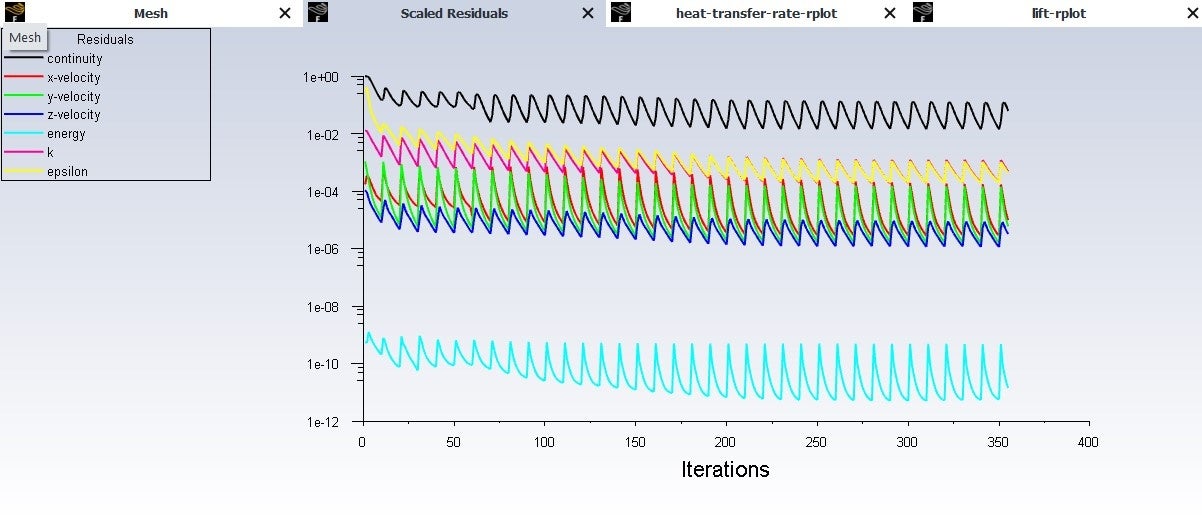
Secondly, please guide me regarding how I should interpret the scaled residuals graph. In some of my other simulation projects, these curves seemed to "flatten out" to a straight line after many iterations, whereas here, I'm seeing a nice periodic and oscillating curve form. How to tell from this curve whether the simulation is proceeding "the right way"?

February 21, 2022 at 12:06 pmRob
Forum ModeratorThe residuals look very transient - are you solving transient or steady? For moving mesh it should be the former, and check each time step converges.
The viscosity ratio can be linked to poor mesh, but is more often down to boundary conflicts or domain scale. The former is where you set a very high (or low) value for k, e, intensity etc which the solver finds to not tie up with the flow field. The latter is for very big domains where the size of the turbulent eddies give high turbulent viscosity.
Check plots of k, e, w etc to see what's going on.
February 23, 2022 at 3:36 amHPatil
SubscriberYes, it is a transient solution. Well, I think it has to be, since I want to show the vortex propagation at different flow times. Can't moving mesh be enabled for a transient solution?
Secondly, just based on the Scaled Residuals graph, is it possible to figure out if the simulation is running correctly? So, for example, in the above graph, what does the periodic and oscillatory nature of the residuals signify? Are there any other conclusions we can draw from it?
February 23, 2022 at 2:23 pmRob
Forum ModeratorMoving mesh needs to be transient as the geometry position changes with time.
When running transient you're looking for convergence in each, and every, time step. The saw tooth plot implies that you're either getting convergence (good) or hitting the max iterations per time step (generally not good). Look at the messages in the TUI. If you're not getting convergence in 10-15 iterations you need to reduce the time step.
February 23, 2022 at 5:22 pmHPatil
SubscriberMy apologies, I interpreted incorrectly. Yep, quite obvious that moving mesh has to be transient. How silly of me :)
Yes, for most time steps, it was hitting the max. iterations (10) per time step. Only in a few of them did I get convergence at the 9th iteration.
Thank you for your help. I still haven't found the time to look at the dynamic mesh tutorials, so I will get back to you once I do. Please keep this thread open.
RegardsViewing 18 reply threads- The topic ‘Fluid Cavity not moving with the Solid Domain’ is closed to new replies.
Innovation SpaceTrending discussionsTop Contributors-
4708
-
1565
-
1386
-
1242
-
1021
Top Rated Tags© 2026 Copyright ANSYS, Inc. All rights reserved.
Ansys does not support the usage of unauthorized Ansys software. Please visit www.ansys.com to obtain an official distribution.
-


Ansys Assistant

Welcome to Ansys Assistant!
An AI-based virtual assistant for active Ansys Academic Customers. Please login using your university issued email address.
Hey there, you are quite inquisitive! You have hit your hourly question limit. Please retry after '10' minutes. For questions, please reach out to ansyslearn@ansys.com.
RETRY


