We have an exciting announcement about badges coming in May 2025. Until then, we will temporarily stop issuing new badges for course completions and certifications. However, all completions will be recorded and fulfilled after May 2025.
Fluids

Fluids

Topics related to Fluent, CFX, Turbogrid and more.

FLUENT MultiPhase – floating point exception 6hrs into calculations

    • Samantha Fedorenko
      Subscriber

      Context of simulation

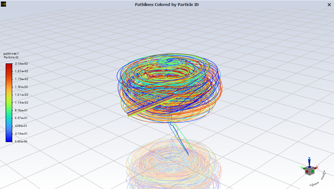
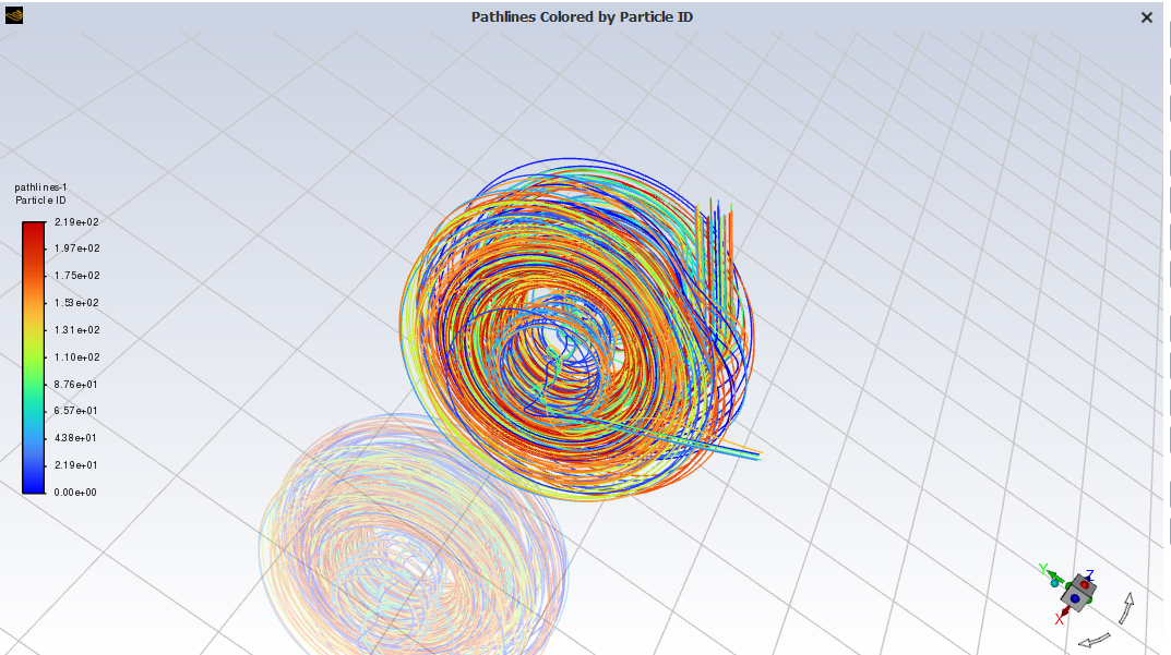
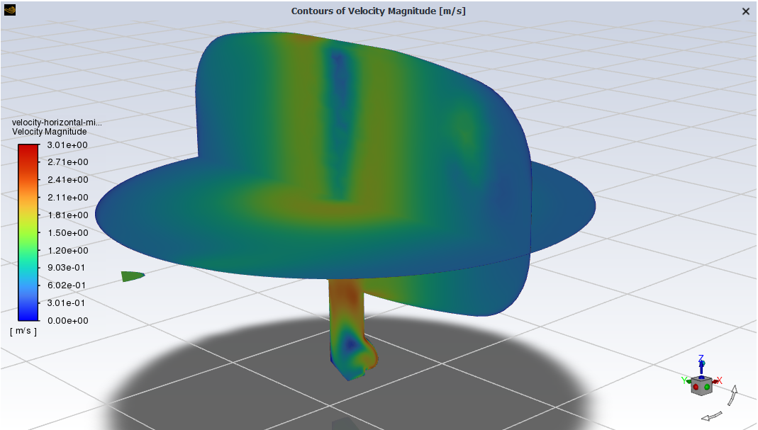
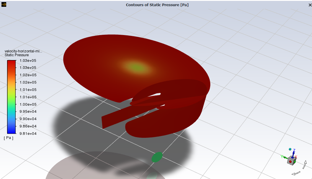
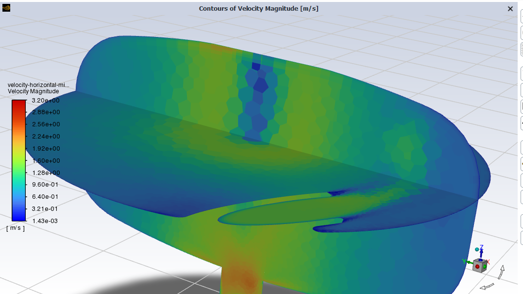
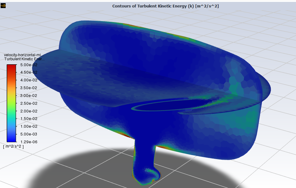
      I am simulating a bubbly flow, where bubbles of 0.2mm at a volume fraction of 0.2 enter the inlet at the side, and go into a chamber where (ideally) the bubbles separate from the liquid, and the liquid goes down the 'plughole' and exits the model. Due to instabilities with steady solutions, I am using a transient solver. There is also a degassing boundary in the model. See the image below for an idea of the geometry

      Simulation problem description

      I found in the past, sometimes I couldn't get the simuation running from 'floating point exception' errors. From other forum conversations, it seemed it may have been becuase the programme could not create enough RAM for the solution, which can be solved by making the solution less computationally heavy, such as coarsening the mesh. After coursening the mesh and it started to run for a short time, but it still hit the same warning, which seemed to come after warnings of divergence. I tried to tackle the warnings of divergence by reducing the timestep.

      So after coarsening the mesh and reducing the timestep from 0.001s to 0.0001s (10x smaller), it had wonderful residuals that met convergence criteria (see image) and was solving for 6 hours, until suddely it hit the floating point exception error again and failed to solve. 

      Unfortunately as it was solving overnight, I could not recover any residual graphs or other convergence monitors. The file also has corrupted itself as it can't find its case file, so I cannot retrieve any more data.

      Please could have some guidance on what is causing the solution to reach the floating point exception error and fail to solve after so long successfully running?

      I am aware of poor quality cells in one area because of a sharp corner where the boundary layers collide, but the mesh quality checks show a good mesh. The fact it also ran for so long indicates that the mesh is fine.

      Detailed ANSYS setup

      Mesh cell quality:  Minimum = 0.092485825, Maximum = 0.99967964, Average = 0.9130338. The mesh has a minimum Orthogonal Quality of: 0.09

      ANSYS setup:

      • Eulerian multiphase model, Dispersed
      • Turbulence model K-omega SST with curvature correction
      • Coupled-SIMPLE solver
      • QUICK momentum and volume fraction solution methods
      • Initialisation of zero motion and bubble volume fraction
      • Drag function - default Schiller naumenn
      • Drag modification - none
      • Lift force - none
      • Lift correction - none
      • Wall lubrication force - antal-et-al Cw1=0.01, Cw2=0.05
      • Turbulent dispersion force - none
      • Surface tension effects - none
      • Virtual mass force - constant=0.5
    • Ahmed Hussien
      Ansys Employee

      A floating point exception error can occur due to various reasons. It is important to ensure the quality of your mesh as one possible cause. Additionally, you can consider using adaptive time stepping in Fluent, where the software dynamically calculates the time step size based on the Courant number you define. This approach helps improve stability by decreasing the time step size when necessary.

      To safeguard your data in case of a crash, it is advisable to enable the autosave feature. Autosaving your case at regular intervals, such as after a certain number of time steps, helps prevent data loss.

    • Samantha Fedorenko
      Subscriber

      Thank you for your reply Ahmed.

      I added adaptive time stepping using the multiphase-specific version, but unfortunately after a short time the floating point error exception occured again. I even re-did the model so that the known problem area with a sharp acute angle in the fluid was rounded, and the mesh did not warn about stair-stepping in the mesh, nor any other warnings . The minimum quality was 0.11 at a different area than before. Unfortunately both times the floating point error exception occured again.


      Both times the same sequence seems to occur where it detects divergence in the AMG solver.

      Are you able to help with this issue further?

    • Samantha Fedorenko
      Subscriber

      I further experimented by changing the model and refining the mesh, so that there were no acute angles in the model space, as they were rounded, and that mesh refinements were done so that volume quality was always above 0.3.

      Despite the solution seeming to be converging generally, shown by the residuals and iterations per time step plots, the calculation deteced divergence again before the floating point error returned.

      Please help with this, as I have tried everything I know to reduce problems with the mesh and added adaptive time stepping to control the model instability. 

    • Samantha Fedorenko
      Subscriber

      I forgot to mention that in the last attempt, I removed the degassing boundary in case that was causing issues.

    • Rob
      Forum Moderator

      Can you post an image of the velocity and pressure on the z-plane through the inlet?  Adaptive time stepping is good when the solution is stable, or flow timescale changes slowly; for an unstable system use a fixed step. How much mesh do you have towards the core, ie where the vortex might form? 

    • Samantha Fedorenko
      Subscriber

      I don't have any planes set up to be able to take a section through the inlet pipe, so this is the best I can provide...

      Velocity

      Here is the inlet velocity setup

      But this is what is given when I ask for the vectors across the inlet at the point. I see these velocities don't make sense, as there should be some velocity at the inlet. As mentioned in the first post, the initialisation assumed no velocity in the volume.

      Pressure


      Mesh

      In terms of the mesh, it become coarser in the middle, being much more refined at the boundaries. The maximum cell length is 0.004m (4mm).

    • Samantha Fedorenko
      Subscriber

      This is the mesh from the another orientation 

    • Rob
      Forum Moderator

      Use the iso-surface tool to create some surfaces - they're critical to understanding the flow field. From the pressure field you also want one in the (roughly) x-plane that lines up with the outlet pipe. 

    • Samantha Fedorenko
      Subscriber

      Pressure of a plane of the inlet nozzle

      and velocity

    • Samantha Fedorenko
      Subscriber

      I tried to setup the iso surfaces,but do to the lack of variation, you can see nothing, so what is above is the best I could find to get something visible.

    • Rob
      Forum Moderator

      Alter the range, I suspect you've got a small region with a silly value. So,   0 < velocity < 5 m/s as a starting point.  Without seeing a flow field it's virtually impossible to assist. If you switch to single phase and steady state how does the flow behave? 

    • Samantha Fedorenko
      Subscriber

      Thanks for the suggestion. I hadn't realised the auto-range was so badly chosen.


      I will get back to you with the static behaviour of this current model, but before I made model changes, I did try static simulations originally. Here's the residuals from the static simulation I did. The mesh quality for this would be similar to the mesh of the first post.

    • Samantha Fedorenko
      Subscriber

      Here's other monitors I set up to track the convergence of the solution.


    • Rob
      Forum Moderator

      The reason for looking at the single phase steady case is it'll work/fail fairly quickly. That makes trouble shooting much quicker. 

    • Samantha Fedorenko
      Subscriber

      Hello Rob, I have made a copy of the simuation with the only change being the steady state. It failed within a minute or two with exactly the same errors. I realised that I had set the inlet gauge pressure, but not the outlet. I believe that may cause some issues with the simulation, as when I set the pressure to the same as the inlet, it started calculating!

      Could you let me know if this could have been the cause of the problem with this simulation?

    • Samantha Fedorenko
      Subscriber

      It turns out that wasn't the problem (or at least the only one) as a few minutes into calculation, the floating point error returned.

    • Samantha Fedorenko
      Subscriber

      Here's the residuals from the steady state simulation with two phases:

      Here are the residuals from the single phase steady state version which is continuing to calculate, but seems it has settled in a non-converged state with what look like high frequency fluctuations within larger waves of less amplitude:


    • Rob
      Forum Moderator

      OK, the single phase results could be useful. If you plot the flow contours what do you see (post here please so I can comment). 

    • Samantha Fedorenko
      Subscriber

      Here's some results of teh single phase results at the cycling non-converged state:

      pathlines show what you woud expect, that the flow enters and flows around the chamber multiple times, and there's a vortex in the middle leading down to the exit 'plug-hole'.

      Flow velocity contours at various planes over the model

      Pressure at various planes over the model

      Turbulence is consistent over the entire model

    • Rob
      Forum Moderator

      OK, I think you need to do some reading on precessing vortex cores. Replot the two velocity contours with node values off and zoom in around where the core is forming. 

      Turbulence isn't constant, it's just below 0.026 m2/s2 in most of the domain. If you look on the contour panel you'll see "Auto Range": it's not always helpful. 

    • Samantha Fedorenko
      Subscriber

      Thank you Rob for your guidance. I now see that the mesh needs refining in the centre, as there is a fairly rapid velocity change in the centre.

      I see the auto range was very poorly chosen for turbulence. The results are better with manual scaling.


    • Rob
      Forum Moderator

      Mesh: yes, and you can also see the jet diffusion from the inlet. 

      Auto range is "correct" in that it's picked up the high and low values. It's just not overly useful for what you're wanting to know. 

      Meshing in CFD isn't quite as straightforward as you may have thought. We have to resolve the geometry (easy, we can see that) but also where we think flow gradients might be. In this scenario it's more difficult as the flow will produce the gradients more so than the geometry: I've modelled a few cyclones and vortex amplifiers so know what to look for. Rather than going back to meshing (not a bad idea to do that but leave that for later) have a look at region adaption. Use that to refine the region around the vortex core, and continue the steady run from the above result: that will show you more of what's going on fairly quickly. 

    • Samantha Fedorenko
      Subscriber

      Could you guide me to which section of the 'Domain' tab to perform this region adaption? Is it 'Zones' or 'Adapt'? Or is it somewhere else? I am unfamiliar with this tool you mention.

    • Samantha Fedorenko
      Subscriber

      Through another forum post, I've found the tool (Can’t find Region adaptation in ansys fluent)

    • Rob
      Forum Moderator

      There may be more information in the Knowledge resources (under Search) too. 

    • Samantha Fedorenko
      Subscriber

      After refining the mesh in the vortex, using the region adaption tool, It still got stuck in a non-converged state.

      The results show the velocity difference better

      A display of vectors shows a better resolved flow, but also shows the central vortex is in an S-shape. I feel the fluctuations in the steady simulation are a result of the vortex 'wobble' that is not stable. This does not answer why the multiphase steady state simulation has not been running, though.


    • Rob
      Forum Moderator

      That sounds reasonable: vortex cores are known to wander around, Prof Nick Syred did a lot of work in the field. 

      We're happy that the single phase model is unstable and inherently transient. Given multiphase tends to be less stable (and far more transient) would you expect it to be easier or harder to get a good result? Also, with a vapour/gas in the domain where do you think it'll collect, and then go? 

    • Samantha Fedorenko
      Subscriber

      I know that for this model, the gas should collect at the very top, where in reality there is a vertical tube that collects the gas. During operation the internal pressure builds with the build up of gas, so the liquid level can vary, meaning that this simulation with a collection of gas at the top is not too dissimilar from reality. I did include a degassing boundary (where the vertical tube joins the model) initially, but was removed during this troubleshooting. The reason for this model is to check if the gas manages to find its way into the 'plughole' where it should not go.

      I know from my attempts previously, that the models within multiphase can make it very difficult to achieve a good result. In the past I excluded the additional optional models, such as the virtual mass and others in the options, as it was the only way it would run. But to get realistic results, I know I need them.

    • Rob
      Forum Moderator

      Yes. And in steady you'll probably finish up with gas slugs in the outlet pipe. Degassing may help, but it's really designed for a stable free surface condition as there's not a pressure value set. Boundary conditions here aren't straightforward as you may find you need to balance the gas vent against the liquid outflow. 

    • Samantha Fedorenko
      Subscriber

      I changed some settings in the multiphase transient model, such as the mesh (much more refined), and the oulet and inlet pressure be the same (100,000Pa gauge). After 3000 iterations, before the flow managed to escape far from the inlet nozzle, the floating point error returned. 

      According to the logs, it detected backflow at the outlet and then divergence, and then the floating point error.

      Here are the results at the 3000th iteration:

    • Rob
      Forum Moderator

      Volume fraction may be a good one to plot too. But, yes, that's failed. 

Viewing 31 reply threads
  • The topic ‘FLUENT MultiPhase – floating point exception 6hrs into calculations’ is closed to new replies.