TAGGED: #fluent-#cfd-#ansys
-
-
November 14, 2024 at 10:08 pm
hmanatunga
SubscriberHi,
I am trying to solve a species transport model (no reactions) coupled with LES k-equation. I have a fuel jet in the middle and a surrounding oxidisier co-flow. The upstream section of the fuel jet includes a converging nozzle. The fuel jet inlet is specified as a mass flow inlet.
I am using PISO with the Ideal Gas law used as the equation of state.
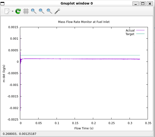
I have specified the mass flow rate at the fuel-jet inlet, and I am monitoring the mass flow rate at the inlet surface using a surface report. The following plot of this surface monitor (Actual) plotted along with the specified value at the inlet boundary (Target). The total temperature was calculated assuming isentropic conditions. The inlet mach number is very small so the total temp is equal to the static temp.
Why is the actual value different from the specified value? -
November 15, 2024 at 10:11 am
Rob
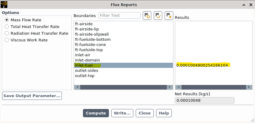
Forum ModeratorPlease can you check the Mass Flux Report in Fluent. Not the surface integral if that's what you were using.
-
November 15, 2024 at 9:50 pm
-
-
November 19, 2024 at 9:19 am
Rob
Forum ModeratorPlease can you post the inlet bc panel? The Forum's been down hence the delay.
-
November 19, 2024 at 10:35 pm
-
-
November 20, 2024 at 10:01 am
Rob
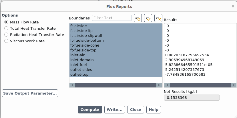
Forum ModeratorWith 3D that should work as you're reporting the same surface. How do the other boundaries tie up with the reports?
-
November 21, 2024 at 5:26 am
hmanatunga
SubscriberThanks Rob for looking into this.
inlet-fuel is the only mass flow boundary. There is a co-flow boundary of type velocity-inlet that is defined as 1m/s in the direction normal to the boundary. There is also a larger pressure-inlet surrounding the co-flow boundary with gauge pressure set to 0 Pa (Operating pressure is 101325 Pa) The rest of the domain boundaries are pressure outlets with gauge pressure at 0 Pa.
Why do you think the reported mass flux through the inlet-fuel different from the one that is specified at the inlet bc panel? Would the non-reflective acoustive wave model have anything to do with this?
I first came across this issue trying to run a non-premixed model of hydrogen jet flame using compressibility effects.
Below is the latest flux report from my last saved dat file
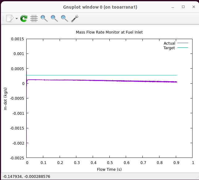
The latest plot of the surface monitor: It decreases over time
-
-
- You must be logged in to reply to this topic.


-
4683
-
1565
-
1386
-
1242
-
1021

© 2025 Copyright ANSYS, Inc. All rights reserved.


