

TAGGED: ansys-cfd, console, fluent-mesh, mrf
-
-
May 27, 2025 at 5:52 am
kelvin.k.kong
Subscriber
EDIT 2: Solved surface mesh issue! I did not subtract the car body from the enclosure, and I did named selections on solids instead of under the Enclosure surfaces (with Enclosure hidden).
I still would like to know how to search for coordinates of issues. Another issue is that I have is with the MRF zones. (See below)
Dear Staff and fellow forum users,I'm trying to following this Ansys learning CFD Learning series.
Importing PMDB file from Discovery to Fluent.
I cleaned up my model using repair and prepare tabs.2 Question of mine:
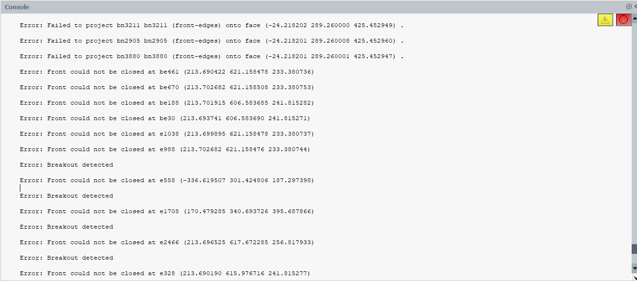
Q1) How to search up the coordinates in Fluent/Discovery to locate the areas of the parts that are causing the issue?
Or any other way to see the issues on the car model?
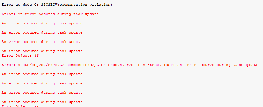
Example:Error: Failed to project bn3211 bn3211 (front-edges) onto face (-24.218202 289.260000 425.452949) .
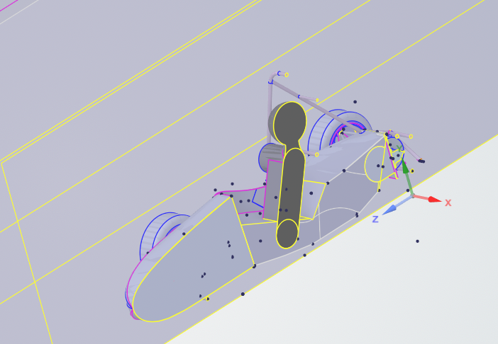
Following the video series, I've created local refinement regions for the front and rear wheels, and three body of influences, created a local sizing for the 'chassis' of the car (everything minus the wheels).
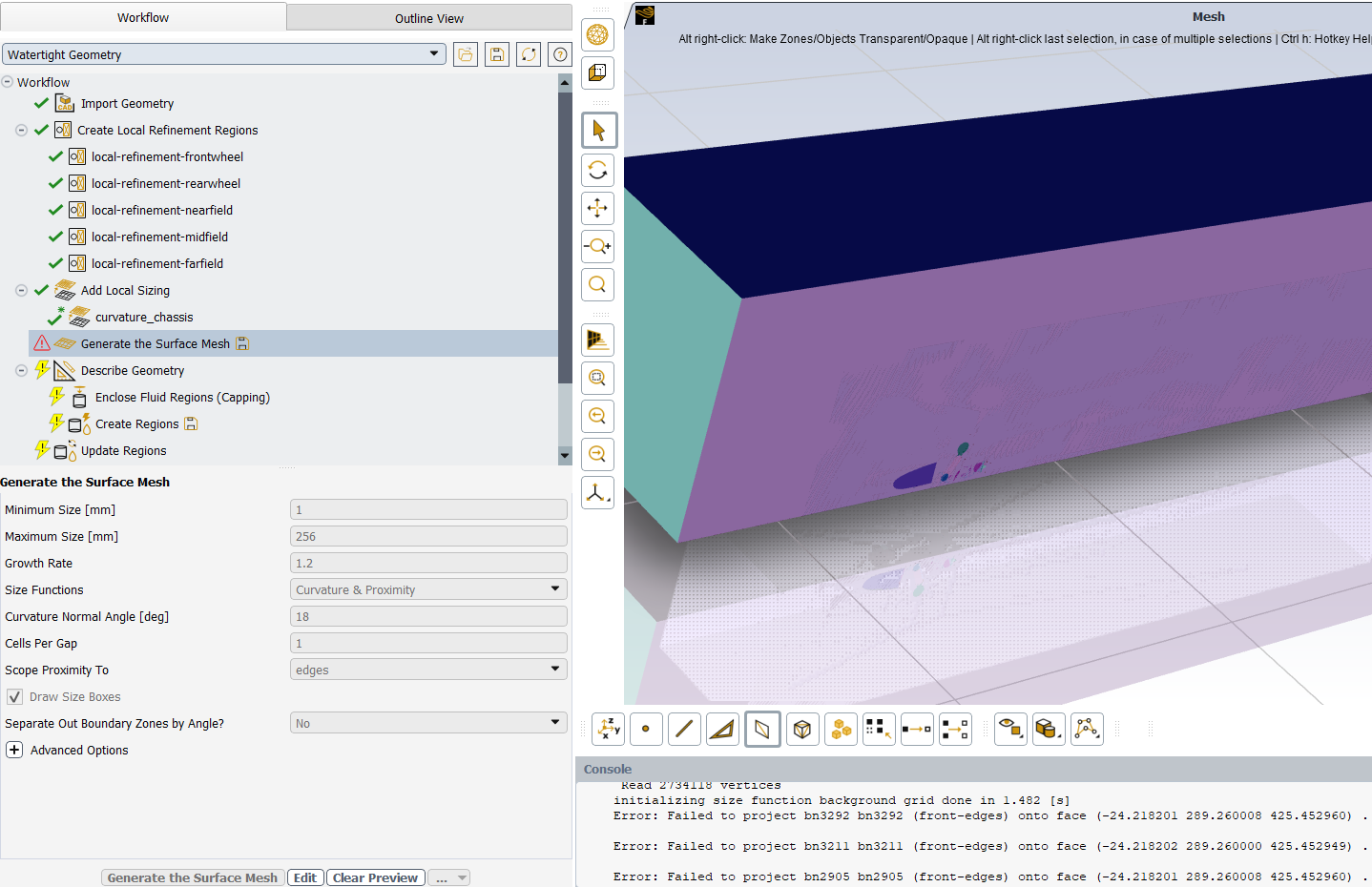
Understandly, error object #f is a meshing problem.
EDIT:
I think I might know what went wrong.
At ~12:45min of this video , the lecturer did 'hide all suppressed' to hide the body of the car, to be subtracted from the enclosure (I guess?). Which I didn't do previously.
Question - Regarding MRF Zones:Regarding MRF zones made in Discovery, and Following this part of this video:
This part of the previous video from above shows the front and rear MRFs as solids, and included in simulation, which I had done.
But my MRF zones does not automatically pop up under 'update regions'.From video:
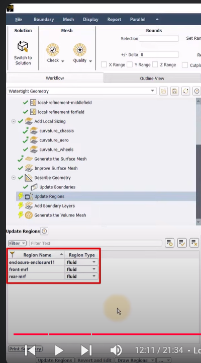
My screenshot: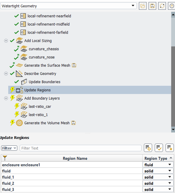
Instead, apart from the enclosure, I have parts called fluid, which are my suspension arms and brake components. (I'm confused!).
Any reason why this is happening for me?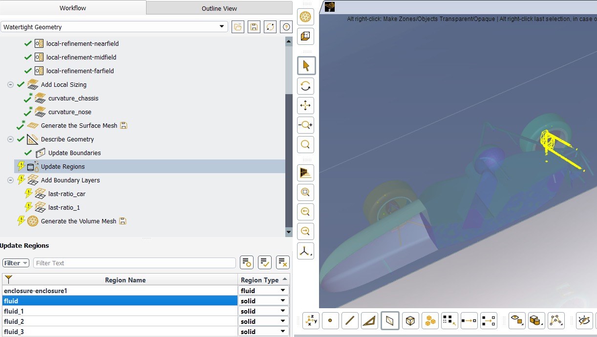
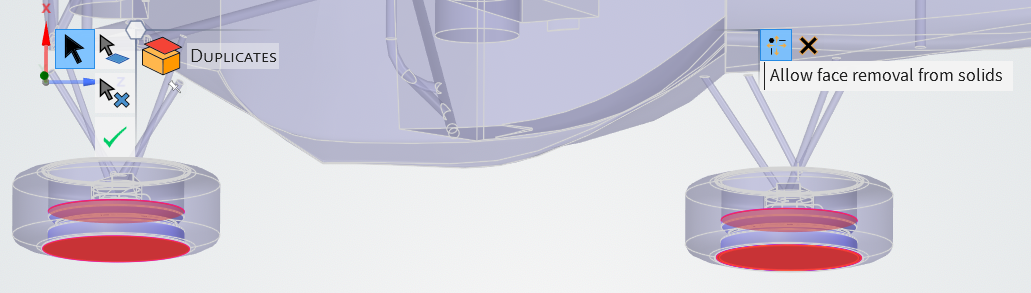
Also in Discovery, my MRFs are inferencing with my rims, via (interference and duplicate tools).
I reckon my overlapping error messages is regarding this! What can I do about this?
Many thanks! -
May 28, 2025 at 7:28 am
Hemant Gurav
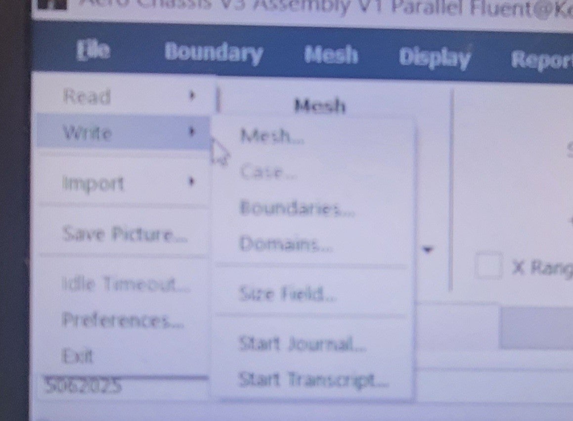
SubscriberTo search for coordinates in Fluent, you can use the following method: In Fluent, click on "File > Write > Profile" and write the coordinates on the surfaces you want to compare. This allows you to export the node locations to a text file, which can be useful for comparing meshes or locating specific areas - https://ansyskm.ansys.com/forums/topic/is-there-any-easy-way-to-check-the-mesh-in-the-fluent-same-as-the-mesh-in-meshing/
While , In Discovery, you can enter the coordinates directly or define the point's origin by clicking "Set remote point location" and selecting a geometry. This feature allows you to specify a point in space for various operations, such as applying displacement or force.Also you can define a point at given coordinates and check the planes for example, check planes at (-24.218202 289.260000 425.452949) .-
June 5, 2025 at 8:43 amSubscriber
Hi Hemantg,
In Fluent, I couldn't find "File > Write > Profile".
In Discovery, exactly under where do I go to "Set remote point location" to enter the coordinates?
Thanks
-
-
May 28, 2025 at 7:40 amSubscriber
Regarding the duplicates, use the duplicate tool in discovery and remove the duplicate solid part. Ensure that you have removed the rims from MRF regions (this might have been mentioned in the video). Assign the MRF regions properly and check it again.This will solve your issue.
-
May 28, 2025 at 11:30 amSubscriber
Hi Hemantg,
thanks for the quick replies.
About the MRF Regions, I am confused what is the difference between MRF and interfaces for the named selections?
(From ~12:06min in this vid)
I don’t know how to obtain the faces for the interfaces. It’s not clear in the video.
Is the Solid MRFs named Interfaces or MRFs in the named selections?EDIT: Managed to use duplicate tool to form the correct mrf!
-
-
May 28, 2025 at 2:12 pmSubscriber
You can download the geometry provided with the course and check the difference between MRF and Interfaces in this case. And yes, you can use/put them under your named selections. Please follow the course link to get the geometries: Aerodynamics of an FSAE Car | Ansys Innovation Courses
-
May 28, 2025 at 4:24 pmSubscriber
Oh, I had forgotten about that! Thanks!
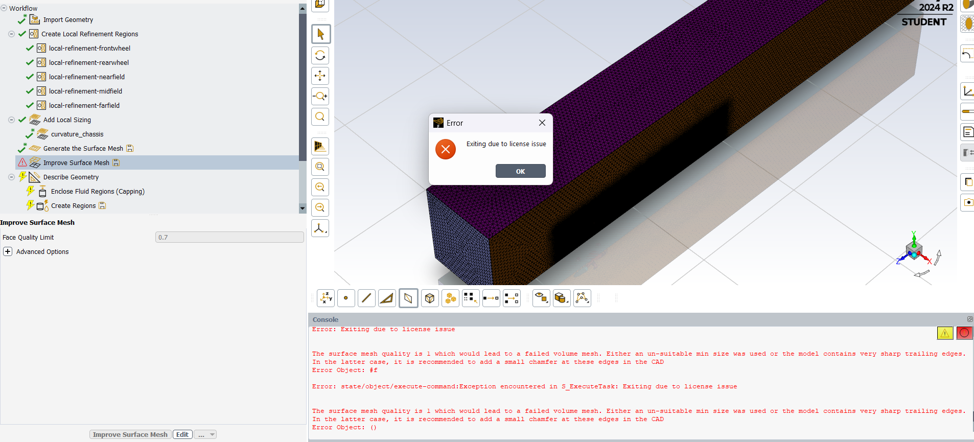
Question – About Surface Mesh
After I tried to improve surface mesh, I always been getting this license issue.
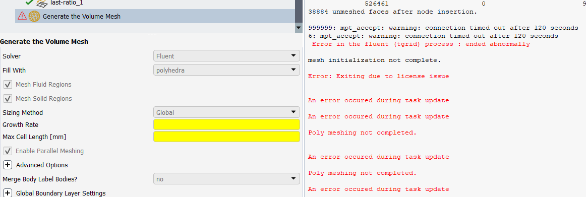
About Volume mesh
Tried with poly-hexcore, this error message appeared:
Error: Exiting due to license issue
Cannot grow prisms.
Mesh object "...solid-body-half-model-test" has no valid Scoped Prisms.
Auto mesh failed.
Tried with polyhedra:
After the failed mesh, Fluent won't let me retry Volume mesh again.
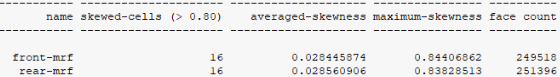
I achieved max skewness of 0.79 prior after improving surface mesh (which is by best so far, as 0.95 seems to be my current best surface mesh (without mesh improvement/or failed improved mesh), of those two volume meshes.
Is it due to my student license?
My uni’s FSAE team just as of last week got sponsored by Ansys! Will that version of Ansys Fluent unlock more meshing power or solve my error issues?Thanks again! :)
-
May 29, 2025 at 1:50 pmSubscriber
Yes, you may try with sponsered license that may unlock some features.
-
June 6, 2025 at 9:15 amSubscriber
“Regarding the duplicates, use the duplicate tool in discovery and remove the duplicate solid part. Ensure that you have removed the rims from MRF regions (this might have been mentioned in the video). Assign the MRF regions properly and check it again.This will solve your issue.”
Hi Hemantg,
I’ve finally able to get front and rear mrfs, by using the combine tool, and subtracting the whole wheel (tyre and rim, from the initial mrf.)
However, I am unable to remove the duplicate errors on the mrfs. (Enabling ‘Allow face removal from solids’, removes the mrfs) No errors pops up under interference.I’ve used share under Share Topology, as seen in this section of this video., if that is meant to help revolve issues, or not…
I am therefore unable successfully surface mesh in Fluent.
Quick edit:
Using the FSAE Lesson 1 Final CAD , it has duplicates issues too. hmmm...
Kelvin
-
-
-
June 6, 2025 at 3:43 pmSubscriber
If you are able to generate the surface mesh, then it's okay. You can try further steps.
-
June 6, 2025 at 4:24 pmSubscriber
Hi Hemantg,
Question 1 about coordinates, Regarding:
To search for coordinates in Fluent, you can use the following method: In Fluent, click on “File > Write > Profile” and write the coordinates on the surfaces you want to compare. This allows you to export the node locations to a text file, which can be useful for comparing meshes or locating specific areas – https://ansyskm.ansys.com/forums/topic/is-there-any-easy-way-to-check-the-mesh-in-the-fluent-same-as-the-mesh-in-meshing/
While , In Discovery, you can enter the coordinates directly or define the point’s origin by clicking “Set remote point location” and selecting a geometry. This feature allows you to specify a point in space for various operations, such as applying displacement or force.Also you can define a point at given coordinates and check the planes for example, check planes at (-24.218202 289.260000 425.452949) .I’ve posted as above using reply, not sure if you had read it:
”In Fluent, I couldn’t find “File > Write > Profile“.
In Discovery, exactly under where do I go to “Set remote point location” to enter the coordinates?”
Edit:
I tidied up the geometry in the wheel assembly (wheel and rim) before combining into a single solid piece. As of writing, I’m able to surface mesh with the mrfs included in simulation.
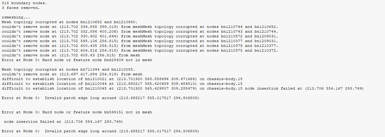
I tried to improve surface mesh, but error message came up.
Question 2: How do I know where the sharp trailing edges are, on my model?
My console log of surface and improved surface mesh:
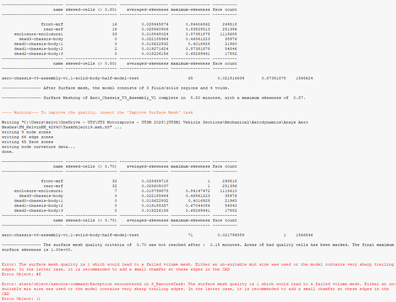
Thanks!
-
June 9, 2025 at 7:48 amSubscriber
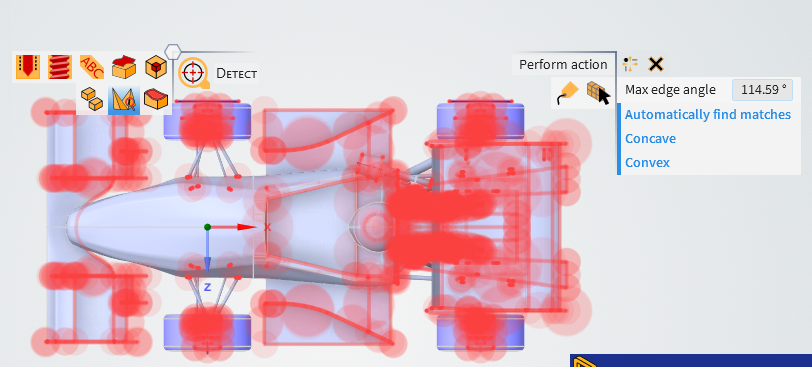
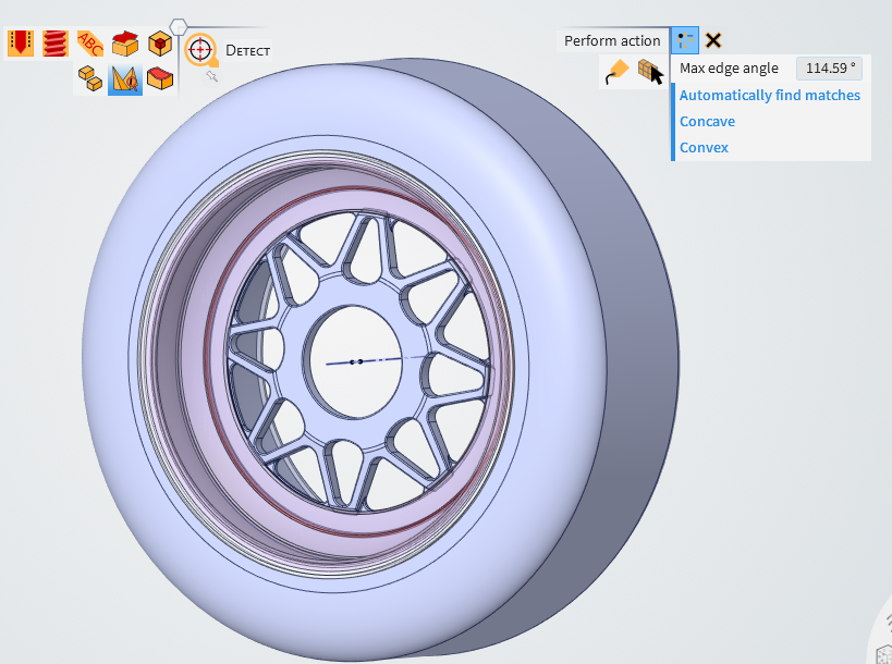
To identify sharp trailing edges on your model, you can use the Sharp Edges tool in Ansys Discovery.follow this
Select Sharp Edges, Go to the Detect tool in the Identify group of the Prepare tab and select Sharp Edges from the dropdown menu. You can enter a Max edge angle in the options panel or keep the default value. This angle is between the normals of faces that share an edge. You can choose to find either Convex or Concave sharp edges.
then Click on Find matching sharp edges to identify edges sharper than the specified Max edge angle in a faceted or solid body. Edges with an angle greater than the specified value will be highlighted. You can also select Automatically find matches to detect matching holes automatically, although this may take longer for large models. -
June 9, 2025 at 7:50 amSubscriber
remove those sharpt edges from discovery , that may resolve issues.
-
June 9, 2025 at 8:02 amSubscriber
Hello again Hemantg,
Looks like I have alot of sharp edges. So for every edge, I need a fillet/chamfer? How do I fillet/chamfer then in Discovery?
How come the repair tools didn't get rid of the sharp edges?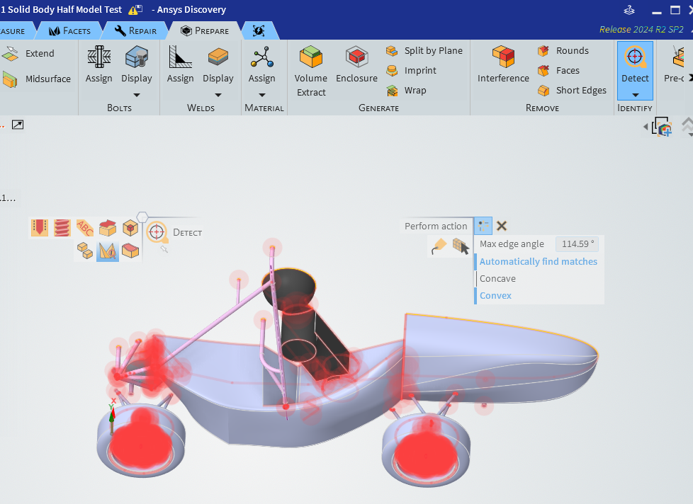
Thanks!
-
June 9, 2025 at 7:51 amSubscriber
Remove sharpt edges from discovery
-
June 9, 2025 at 8:01 amSubscriber
Ohh Okay, got I got that option on my end but its okay(Try with solution mode). You can use another method mentioned , to check the geomtry at the given point. Also while improving mesh cautious when you are setting up the quality.
-
June 9, 2025 at 8:17 amSubscriber
This is the Final CAD from the example model:
It also has sharp edges. So is it really an issue?
From my post above^^,
I will try putting fillets/chamfers on the tyre and rim, since of the surface mesh runs, the max skewness is rather high.
-
June 9, 2025 at 8:48 amSubscriber
can you share zoom in picture, if the edge is too sharp then is it diffucult to generate the cells near those region. Can you champer this or use fillet or remove those sharp edges by other means and try to mesh it.
PS : Please remove only very sharp edges, try with different angles -
June 9, 2025 at 8:51 amSubscriber
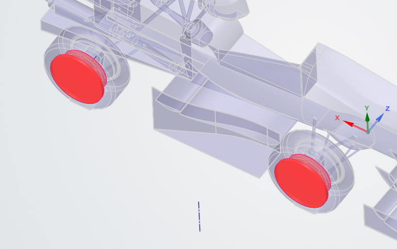
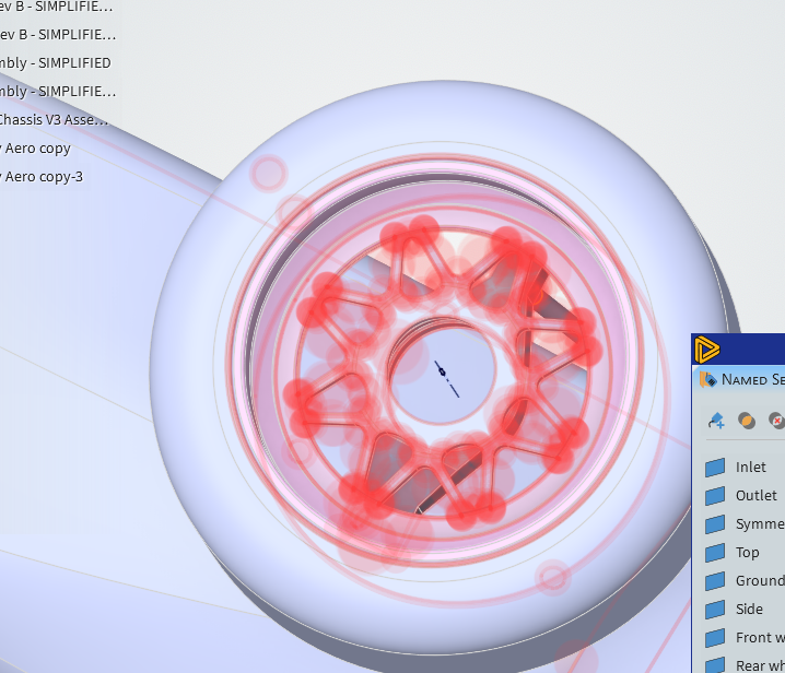
I compared the sharp edges of the wheels of my wheel model to the example model, and it has filleted edges on the rims.
I could not find a chamfer/fillet tool in Discovery.Close-up picture of my wheel:
-
June 9, 2025 at 8:59 amSubscriber
Thou I would suggest to complety remove this rim and replace wih just single solid part. Reason : You are performing flow analysis for entire car not for region near wheels. This effect is negleagible
-
-
-
June 9, 2025 at 8:56 amSubscriber
Use Pull tool , ther you will find champher / Fillet: Attahced SS
Or follow this course How to Use the Pull tool in Ansys Discovery | Ansys Courses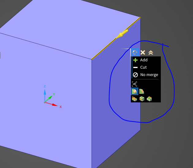
-
June 9, 2025 at 9:46 amSubscriber
Hello again,
I ended up filleted in Solidworks, as it'll take me ages in Discovery. Resulted in one sharp edge showing, which I have deleted, yet still showing.
Regarding Repairs > Missing faces:
I'm having trouble getting rid of missing faces.
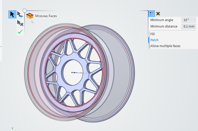
If I proceed to fix the missing faces, it will turn up with the face filled, which we don't want, right?
Thanks
-
June 9, 2025 at 9:52 amSubscriber
Ansys Discovery is easier; you just need to get used to the UI. Yes, you can fill the rims go ahead, as I suggested before.
PS: You can modify your geometry as you wish, just do not repeat the steps. The most important thing is to get the most simplified acceptable geometry of an FS car for flow analysis. I assume you are focusing on drag and lift forces.
-
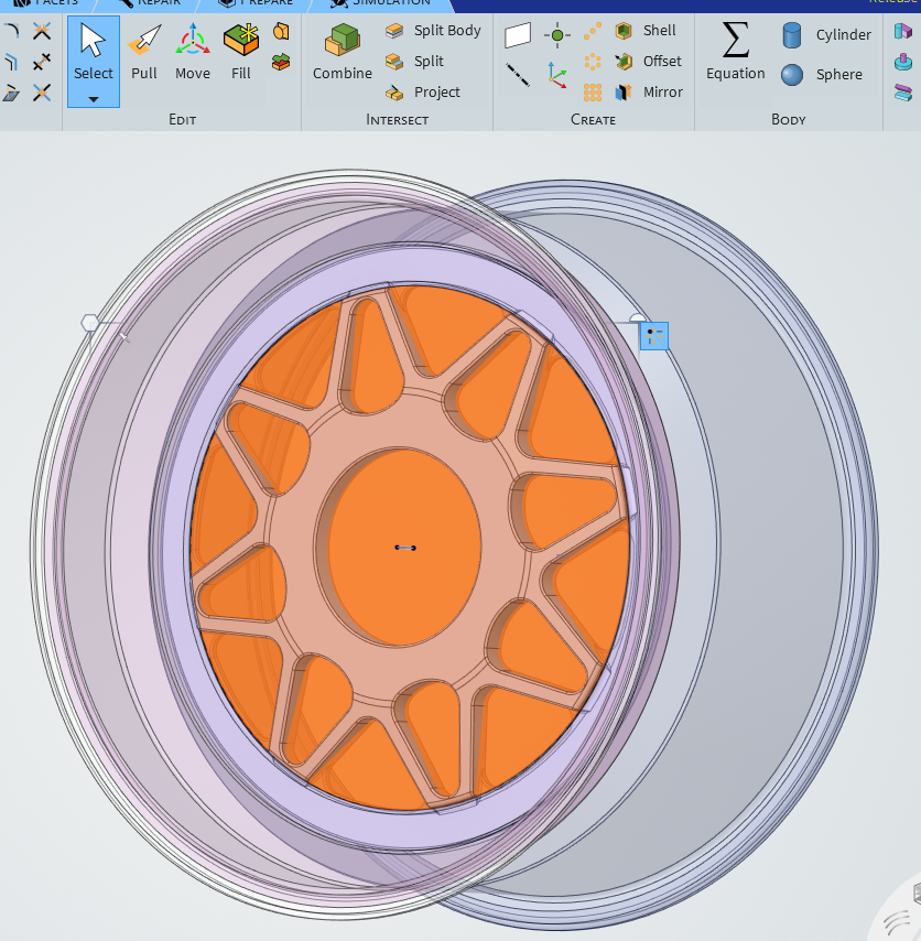
June 9, 2025 at 9:58 amSubscriber
If I fill all the missing faces, it will look like this: =S
-
June 9, 2025 at 5:37 pmSubscriber
It's okay, should work. Please check previous reply
-
-
-
June 10, 2025 at 4:25 amSubscriber
Update:
I'm now able to get my initial surface mesh to max. 0.89 - .95 skewness, with being able to improve surface mesh to 0.70.
However, following the video here , I'm not able to volume mesh with poly-hexcore, same too when I did not have correctly setup my mrfs previously.
Error message pops up, and after exiting the pop-up message, I'm unable to continue make changes to the workflow, and have to close down Fluent.
Why is that?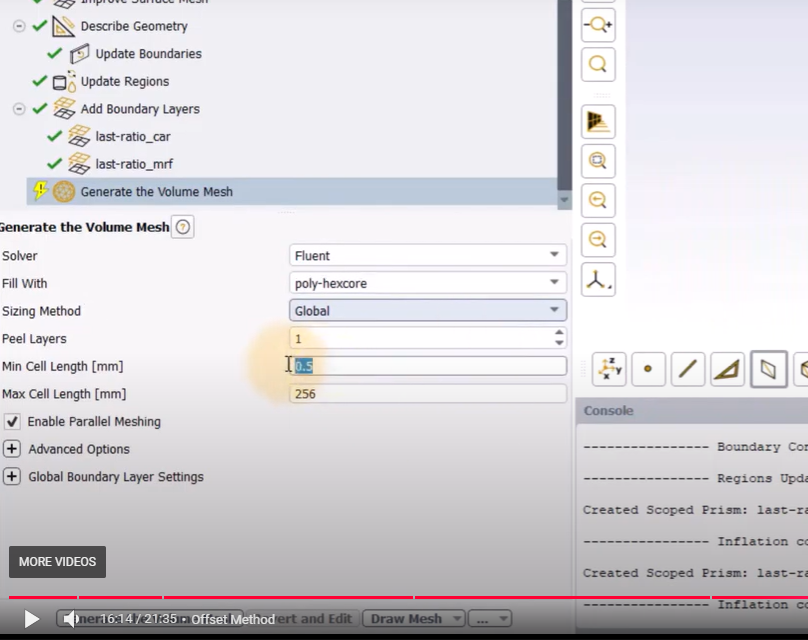
Thanks again.
-
June 10, 2025 at 7:11 amSubscriber
Could you please use the provided geometry with the course and try to generate the mesh? This is a generic error; can you retry meshing with both your geometry and the provided geometry? This should work. Try using different Min max cell lengths and the Fill with method.
Are you using a student license? If so, I recommend increasing the cell size.
-
June 10, 2025 at 7:21 amSubscriber
“Could you please use the provided geometry with the course and try to generate the mesh? This is a generic error; can you retry meshing with both your geometry and the provided geometry?”
What do you mean by this?
Do you want me to provide all my min and max cell lengths?I’m using full academic license.
Thanks
-
June 10, 2025 at 9:39 amSubscriber
You must be using your university FS car geometry?
I recommend you refer to the reply:PS: You can modify your geometry as you wish, just do not repeat the steps. The most important thing is to get the most simplified acceptable geometry of an FS car for flow analysis. I assume you are focusing on drag and lift forces.
Please check the sizing provided in CFD Mesh Generation of an FSAE Car| Ansys Innovation Courses. ( Check attached SS) .. Use these files and try to generate the mesh. (I have checked it for you and was able to generate it, thou i need not to) Then try with your geometry. I cannot provide you min and max cell lengths before just copying the steps( Can use local sising of 4 instaed 2 in volume mesh ), please understand how mesh sizing works (I believe that you know this): Ansys Fluent Meshing Learning Track | Ansys Innovation Courses. Please follow the course if you are new to meshing, understand it, then you can use the local sizing as per your geometry. This should work. Please try to compare the geometry/mesh. I recommend you learn the problem statement thoroughly, what is the end result we are focusing on. As I can see from previous replies, you have overlooked certain issues Hope this helps you.

-
June 10, 2025 at 9:45 amSubscriber
Yes, I'm using my own car geometry, from my FSAE Uni Team.
I'm now stuck on generating the poly-hexcore mesh (as I had mentioned above).
Thanks
-
June 10, 2025 at 9:51 amSubscriber
Please refer above reply and try to regenrate the mesh. It should work. Restart the meshing process. Try with new 2025 student license
-
June 10, 2025 at 10:06 amSubscriber
That’s what I have been doing/following for the past 2 months, using my car model.
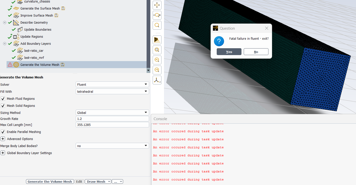
I’m using 2024 R2 Ansys, as I have been doing all my work from that version.Again, I’m stuck on Volume mesh. I tried with tetrahedral mesh (with default max cell length) instead of poly-hexcore. Looks like it too failed to generate:
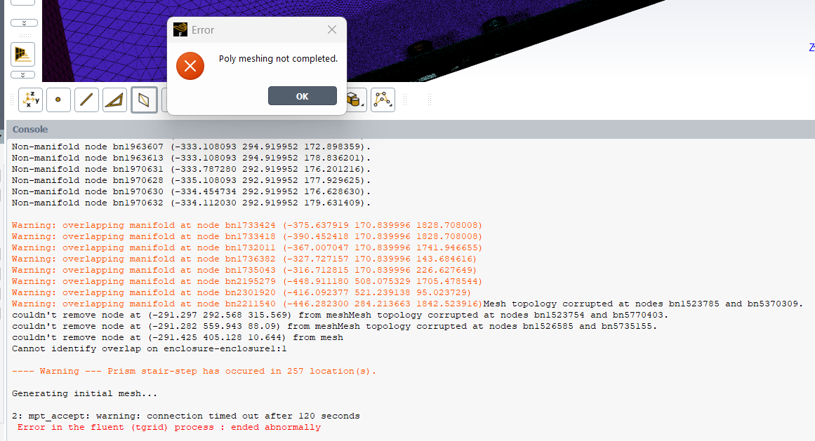
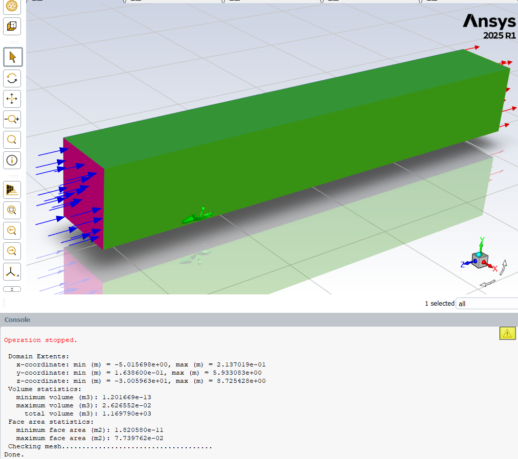
I assume errors like these are geometry errors, but I’ve made sure that I have cleaned up my geometry before making the enclosure, then named selections, before importing into Fluent.
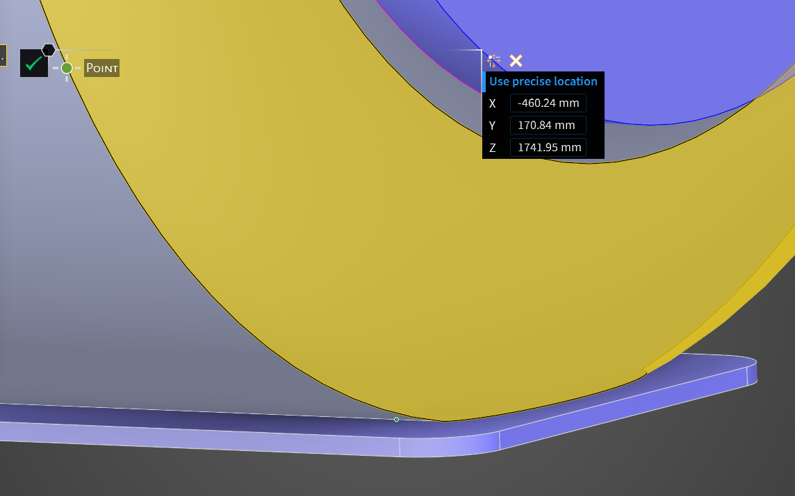
And I don’t know how to search for the parts of the car that are coming up with errors.Non-manifold node bn230054 (10.688354 808.717072 1650.821131).
Warning: overlapping manifold at node bn223983 (-460.244628 170.839996 1741.946655)
Thanks.
-
June 10, 2025 at 10:20 amSubscriber
Have you checked the geomtry i.e attached with the course. Please try with this, fatel failure .. this may have many reasons. memory issues, computer resources , geomtry errors etc.
Non-manifold node bn230054 (10.688354 808.717072 1650.821131).
In the context of finite element analysis (FEA), non-manifold nodes can occur when an exterior node is shared by multiple external edges or faces, which can complicate the meshing process. This is often seen in 3D models where a node is shared by four or more external edges or faces. To address this, you might need to adjust the geometry at the given node or the meshing strategy to ensure that the node is properly integrated into the mesh.
Can you share the zoomed is SS for this node (10.688354 808.717072 1650.821131). and check XYZ co ordinate system for your geomtry. Have you noticed this ? Seems like coordinate system is different in your system . You need to recalculate X and Z cordinates for local refinment and other settings. So i would recommend to mesh the provided geomtry with course understand the apporch thoruoughly and then recalculate the domains as per your geomtry and mesh it.
Please share me SS of Meshed Geomtry( use geomtry from mentioned course) in next reply as provided below,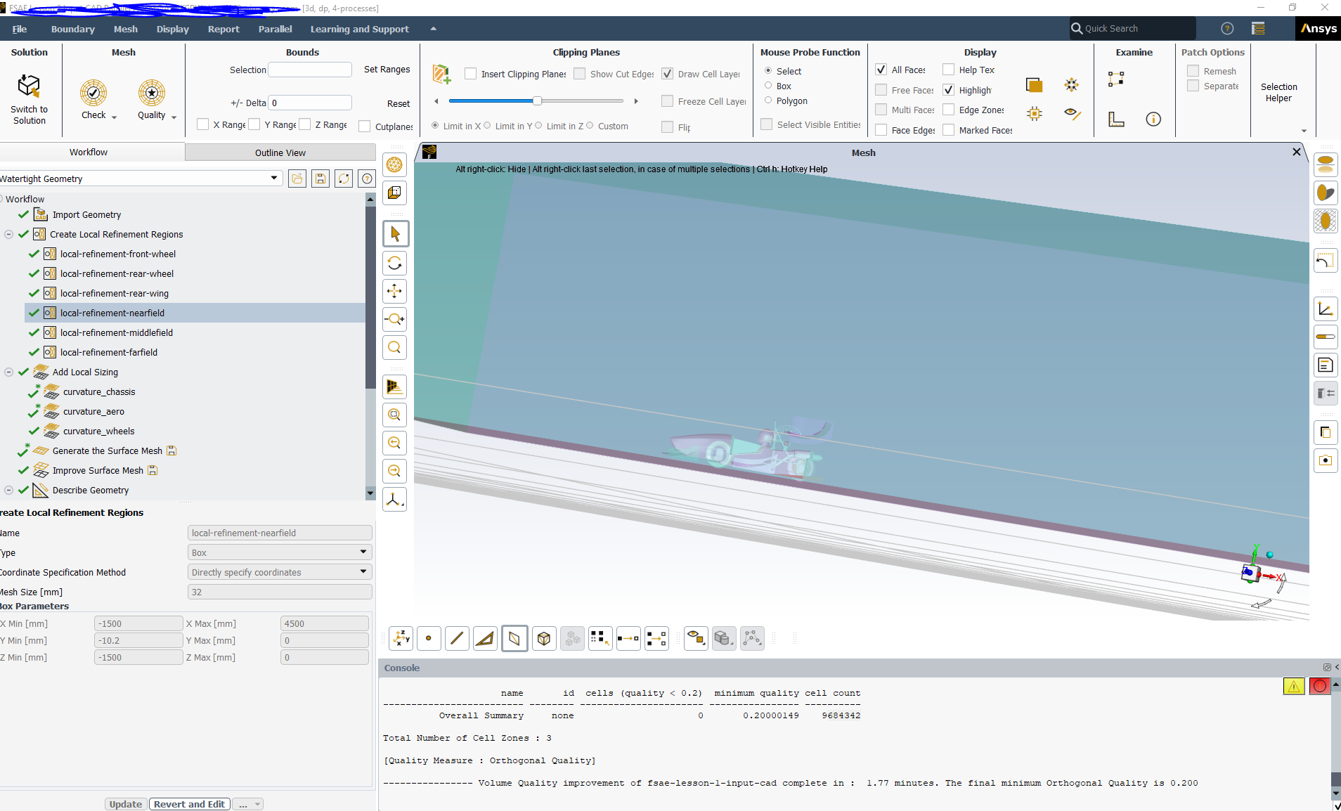
-
June 10, 2025 at 11:26 amSubscriber
Hello Mr Hermant, I appreciate your time on helping me.
“Have you checked the geomtry i.e attached with the course. Please try with this, fatel failure .. this may have many reasons. memory issues, computer resources , geomtry errors etc. “
Yes I have. I remember I have at least succesfully surface meshed with the sample car model.
Question 1: Is running the CPU at near 100% for surface/volume meshing an issue, short term or long term for my computer?
Running with 16 cores on Fluent at the moment (maximum for my license). I have access to add more cores with my team’s uni licenses, since my computer can use up to 28 cores.
My computer (laptop workstation) is quite beefy, as to why I purchased it, to handle computer-demanding tasks.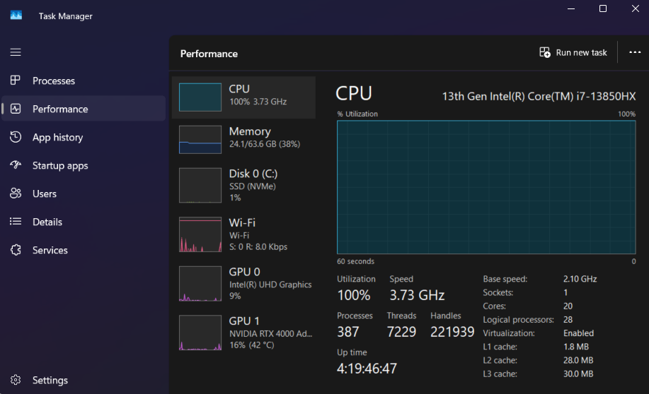
“Can you share the zoomed is SS for this node (10.688354 808.717072 1650.821131). and check XYZ co ordinate system for your geomtry. Have you noticed this ? Seems like coordinate system is different in your system . You need to recalculate X and Z cordinates for local refinment and other settings. So i would recommend to mesh the provided geomtry with course understand the apporch thoruoughly and then recalculate the domains as per your geomtry and mesh it.”
Question 2 – How to search for coordinates: Pardon my noobi-ness, but I don’t know how to enter coordinates in Fluent (or Discovery). That’s why I’m struggling to pin-point the error console messages.
Yes, I realised that my planes are not at origin. I figured that my main planes on my CAD car model is NOT the same as in the Ansys video series.
I have precisely recalculated the coordinates via sketching lines from my planes to the origin of Fluent, in Discovery.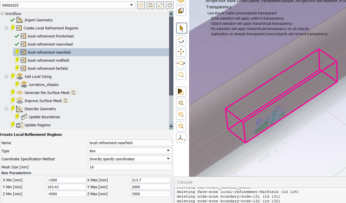
Question 3 - Could you provide me with your work email, so that I can send you my files, if you don't mind to have a look?
Many thanks!
-
June 10, 2025 at 12:55 pmSubscriber
I cant work on you geomtry thou I can guide you .
Its simple in 2025 R1 (please use this version)
Follow this procedure
Create a point from design tab, enter precise location and click on green tick mark. The point will be created at location and check for that green point. And check that location throughly .
Or simply create planes with at that location using plane tool and move tool. I would reccommend you to go through Ansys Discovery course- cad prepparation . You may find the course link in earlier replies- Geometry Prep for CFD using Ansys Discovery | Ansys Courses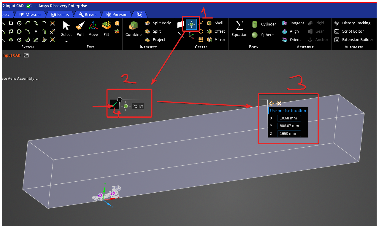
-
-
-
June 10, 2025 at 3:57 pmSubscriber
Hello again HG,
2024 R2 doesn’t have step 3 Use precise location feature. 2025 R1 is downloading at the moment.
I think I have found the issue:
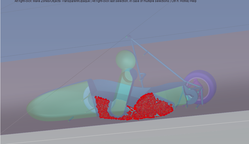
From my last Volume mesh, it meshed, but bad quality.
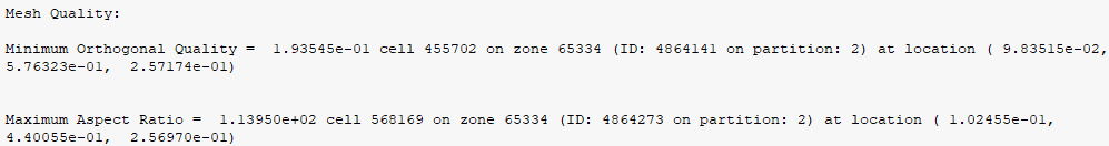
”—————- The volume mesh quality criteria of 0.050 was not reached. Cells below the criteria are being displayed. The final minimum Orthogonal Quality is 0.000
—- Warning— The mesh has a minimum Orthogonal Quality of: 0.00e+00. Bad quality cells are drawn.”
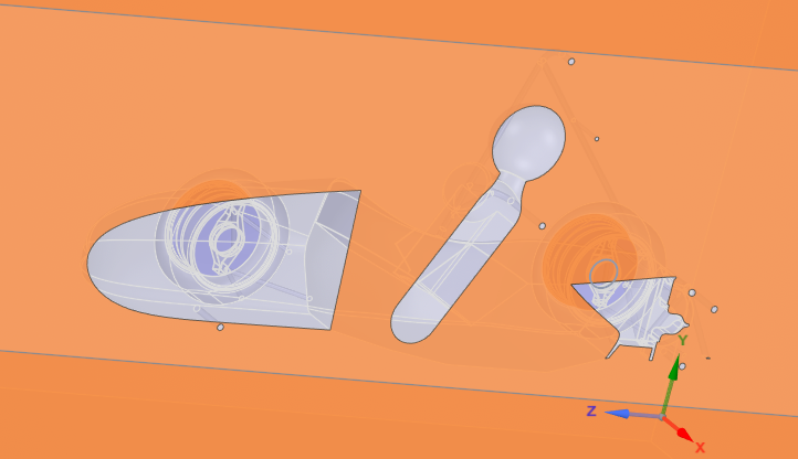
I assume the areas marked in red is the problem.
In the video tutorial, after spilting on central plane of the enclosure, the faces of the body that exists on the central plane dissapears, as shown in the example model:
This is after spilting the enclosure down the central plane. You can see my middle body’s central edge did not disappear. Hmmm, how come?
Update
central line geometry:
I figured out it was the funky central line geometry when a surface lofted half of the centre body, then mirrored it in Solidworks. (Unable to combine them).
I therefore redid my loft surface loft, to loft the whole centre body, instead of half of it.I then was able to split the body in half in Discovery, and after spliting the enclosure down the central plane, I was able to make the central body’s face disappear!
Volume meshing:
Currently volume meshing.
Still getting manifold errors as before.
Initial volume mesh with poly-hexcore resulted in a minimum orthogonal quality of 0.012.
After improving the mesh, with cell limit set a 0.2, the target was not reached, instead the minimum orthogonal quality resulted in 0.067.
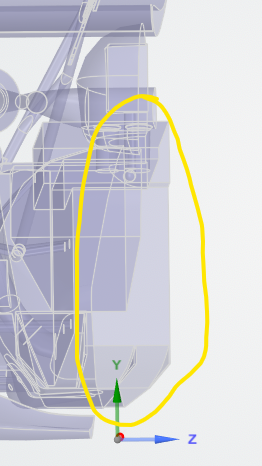
Looks like the outline of my car model, "enclosure-enclosure11" is the issue.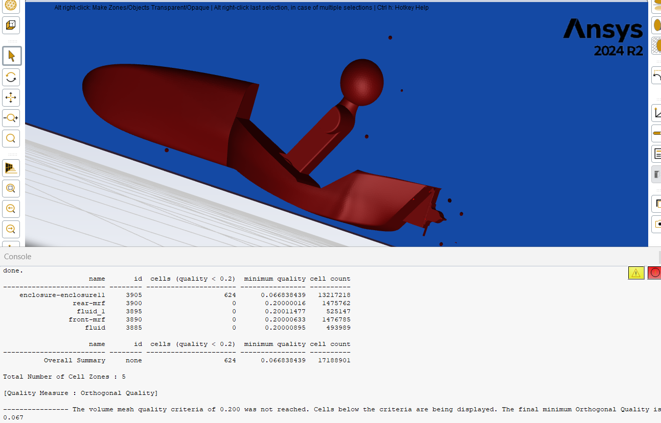
Will go to sleep now, and tomorrow I will continue on, and will try to seek the coordinates of the errors, using 2025 R1.Thanks
-
June 11, 2025 at 4:35 amSubscriber
Using 2025 R1 – Looking up errors coordinates
Non-manifold node bn230054 (10.688354 808.717072 1650.821131):
Looks like around the edge of my body.
Might be because that edge there is very very thin. I will fillet it, and see if it will help.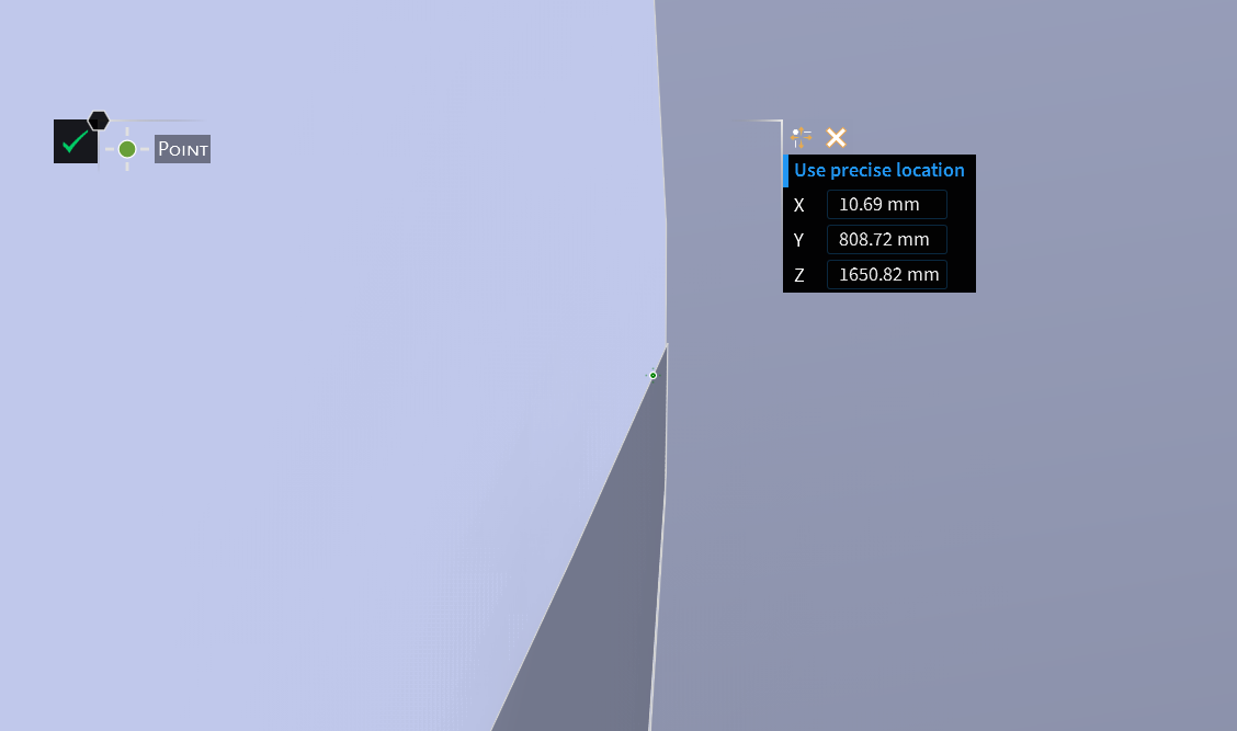
Non-manifold node bn230054 (10.688354 808.717072 1650.821131):
At the edge of the wheel and the patch
Another location at suspension upright and arms (merged together)
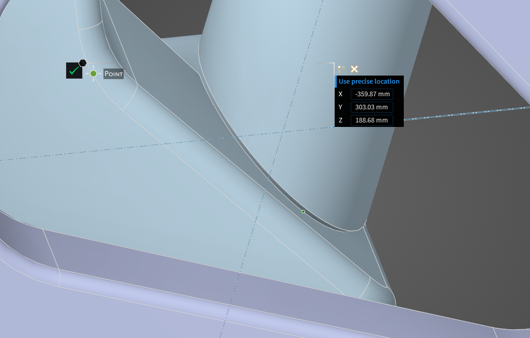
How come Discovery repair tools didn’t repair these manifold issues?
I’ve tried to use shared topology with max gap distance of 0.5 and 1mm, but when it came to Volume mesh, it failed to mesh, or the initial minimum orthogonal quality became worst at 0.0.
Many thanks.
-
June 11, 2025 at 6:50 amSubscriber
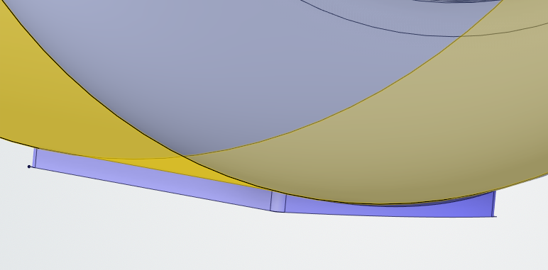
Avoide gap in wheel patch , just check on net how wheel patch should be , Its in the course also. Your is very thin. Fill that gap , use Pull tool (Same as extrude)

-
June 11, 2025 at 7:07 amSubscriber
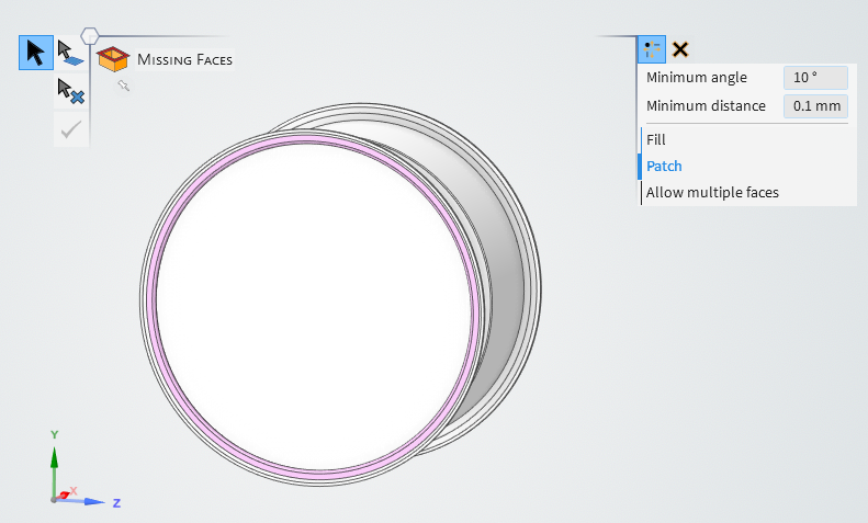
Yes, I have noticed.
I made the patch too large. The video didn’t state exact how small/large to make it.
Does it matter about the width of the wheel patch?Here’s my revised wheel patch.
-
June 18, 2025 at 8:01 amSubscriber
It's your call.. but as I said earlier check the reasoning behind each and every step. Have you read it about this in any of reference material. If not so please clarify these concepts
-
-
-
June 11, 2025 at 6:46 amSubscriber
It's great that you are finding issues by yourself and resolving them too. If you are using another software combined with Ansys Discovery, be careful as there might be conversion issues. I would recommend preparing error-free geometry in Ansys Discovery as shown in the course. That's why the course focuses on geometry preparation. Whenever you see edges, gaps, or anything that may cause issues, just make it solid, fill the gaps, fillet the edges, and simplify the geometry, and you will be good to go. Do you have access to Ansys assistance? You can ask minor doubts like cell quality there.
-
June 12, 2025 at 12:18 pmSubscriber
1 – Post processing
I managed to run at least 50 iterations out of 500 that I had set (when I checked the progress) in post-processing before my laptop crashed (I think) overnight.
Is there a way to make the memory run not maxed out?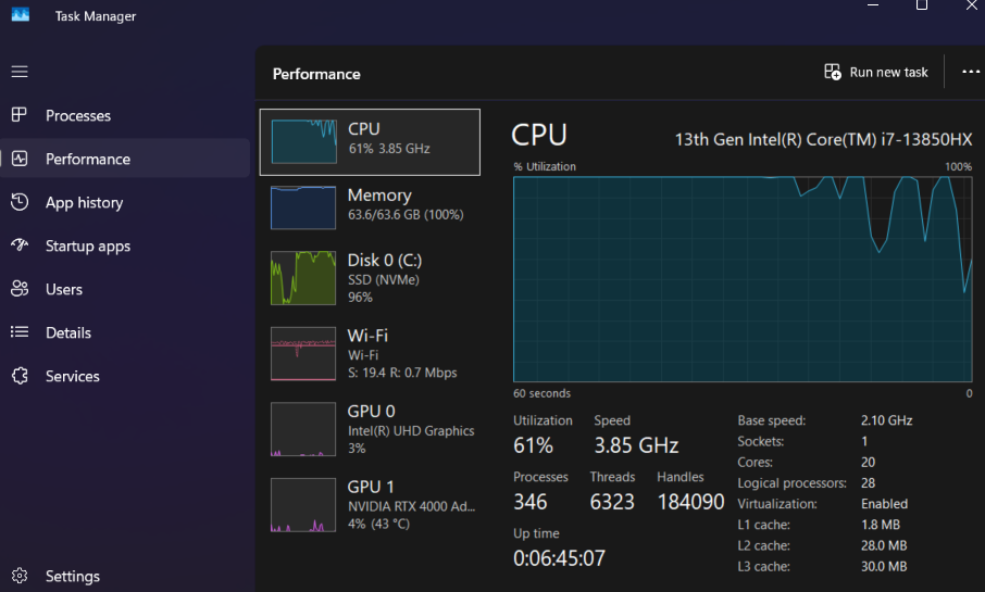
2 Volume Mesh Gap Issue – I tried to fix my non-manifold issues from previously
I think I have successfully fixed my non-manifold issues in Discovery, as no messages are popping up during volume meshing.
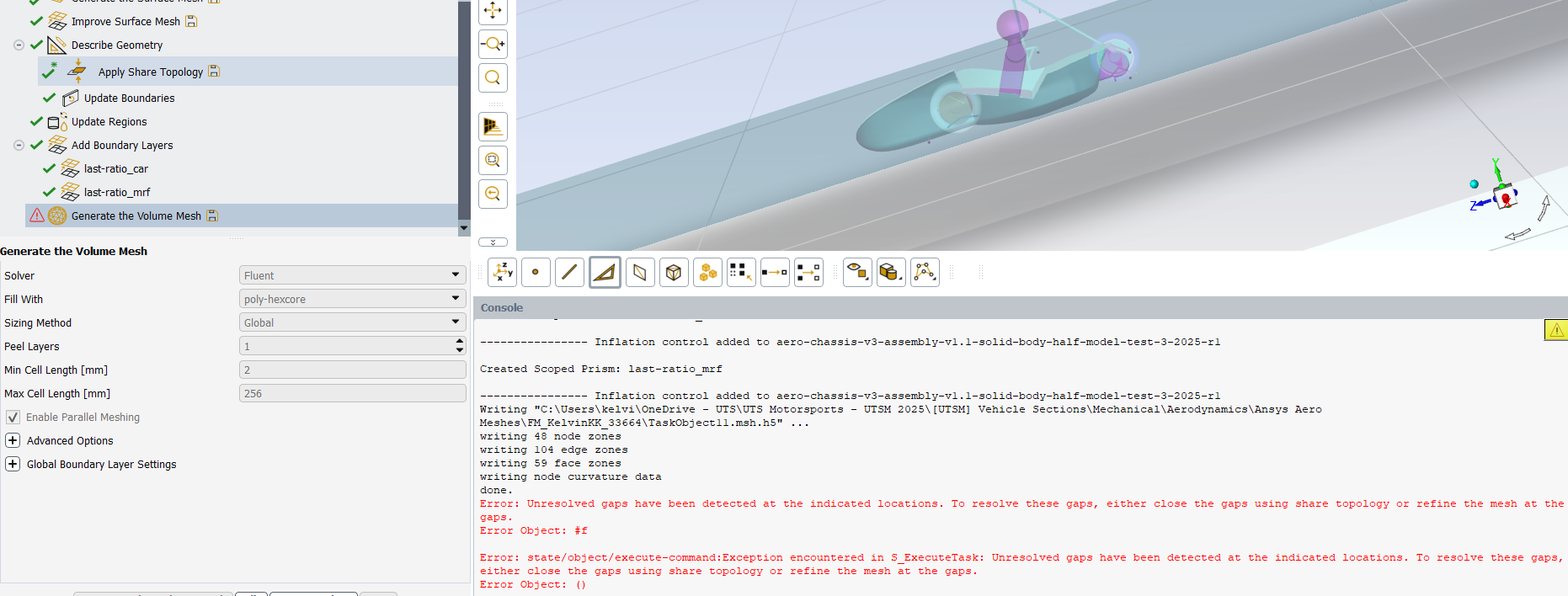
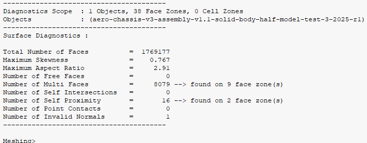
However, I am encountering a gap issue, but I am not presented with coordinates of the gaps in the console. No issues found using the gaps tool in Discovery, so I am not sure what is going on.
I have also used shared topology under describe geometry, I didn’t think it would work as I have already shared topology of the enclosure in Discovery.I don’t know how to check for gaps in Fluent, but here’s the Perform Diagnostic Summary, if it is useful:
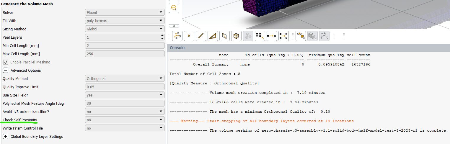
Quick update:
I turned off Check Self Proximity, and was able to mesh. How strange?!
I am unable to use the Ansys Assistant using my Uni Team’s account:

Many thanks, again!
-
June 13, 2025 at 6:58 amSubscriber
Great, you are finding it yourself. Inspect geometry thoroughly you will get the locations/ issues
-
-
-
June 12, 2025 at 5:30 pmSubscriber
In solutions, running calculations, at the start of the iterations, I am getting this message:
Any tips what it could be?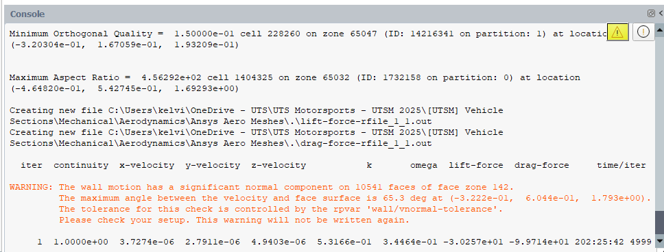
Thanks again.-
June 13, 2025 at 6:59 amSubscriber
Please check your input components and vector resolutions. It seems your values are bit on higher side
-
June 17, 2025 at 12:58 pmSubscriber
Hello Hemant,
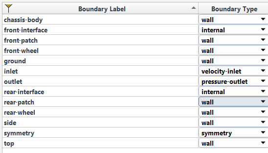
I assume face zone 142 refers to my front-wheel.
But I dunno what I did, how I how the error on the rear wheel.
But following the video, I couldn’t find where I went wrong.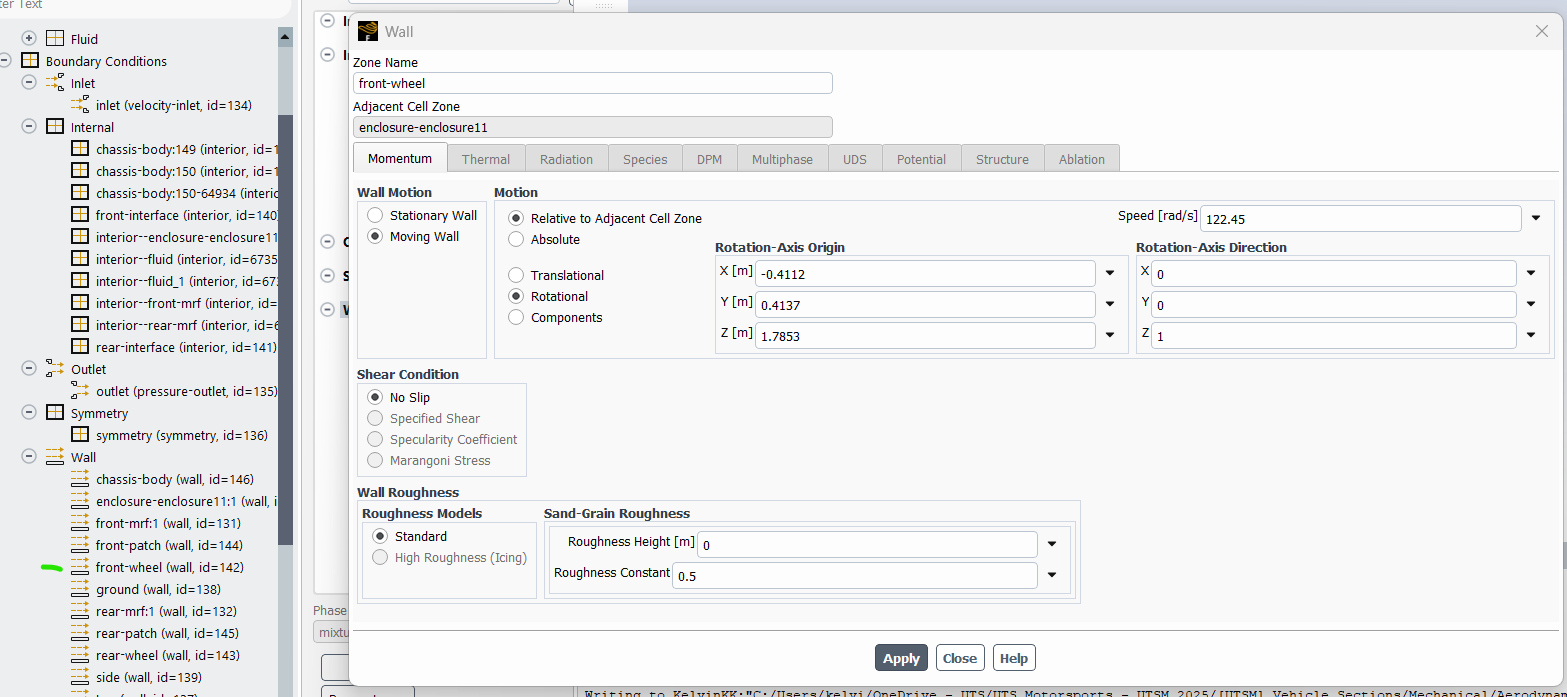
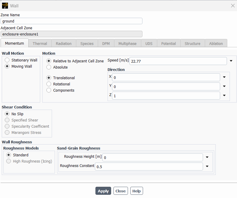
Side and top walls the same:
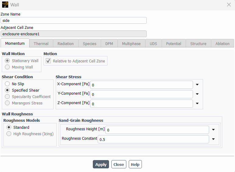
What else do I need to check?
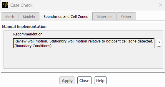
Run Simulation
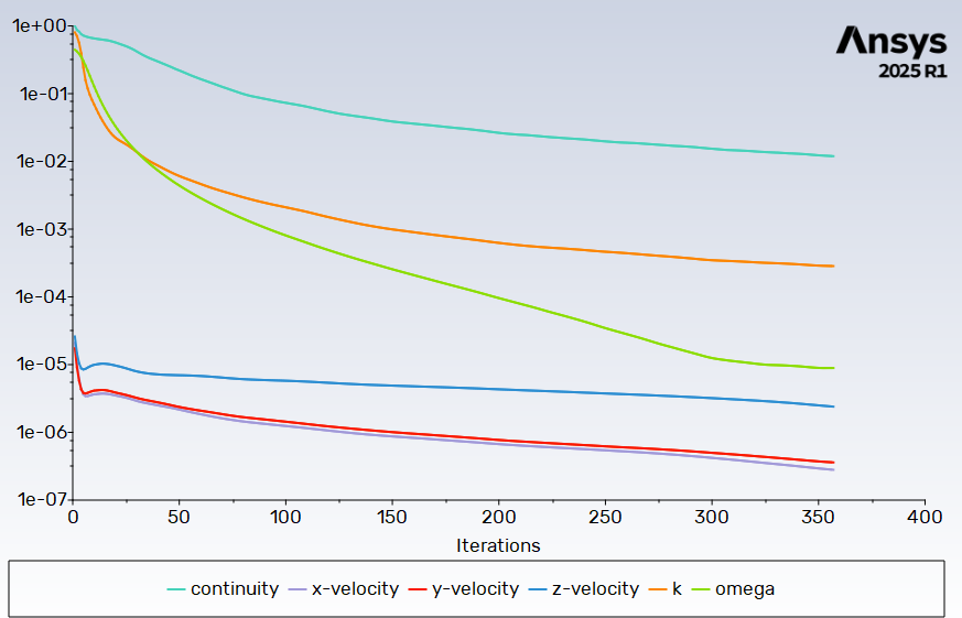
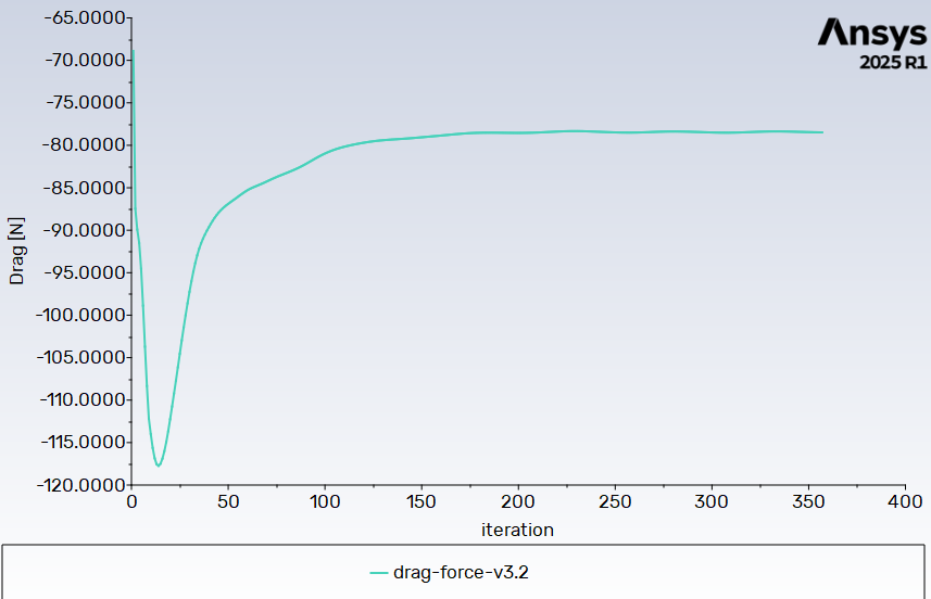
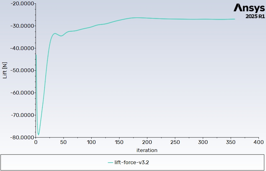
My first iteration of 4000+. The scaled residuals has not dropped by even 1 order of magnitude, and my drag and lift graphs are not stabilising. (note that the direction of the airflow axis is in the opposite direction of the airflow, hence the negative sign)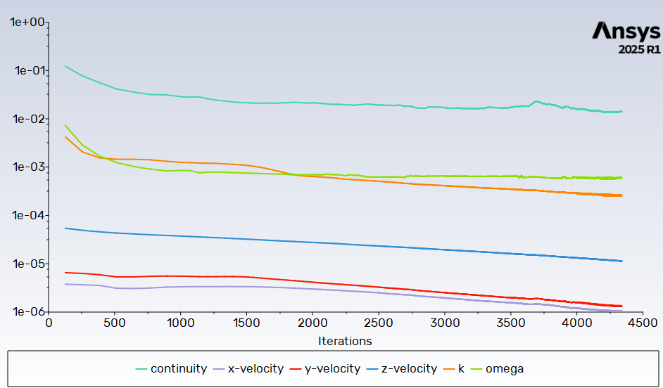
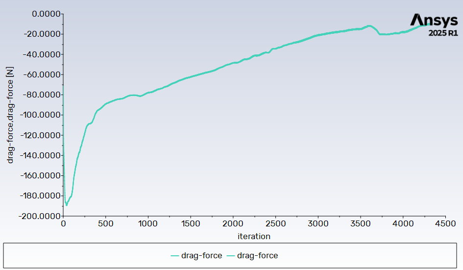
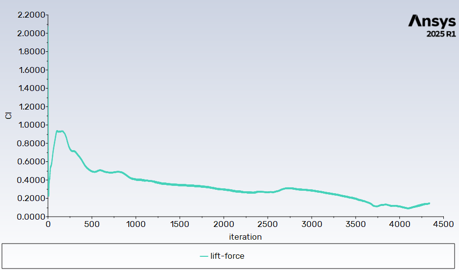
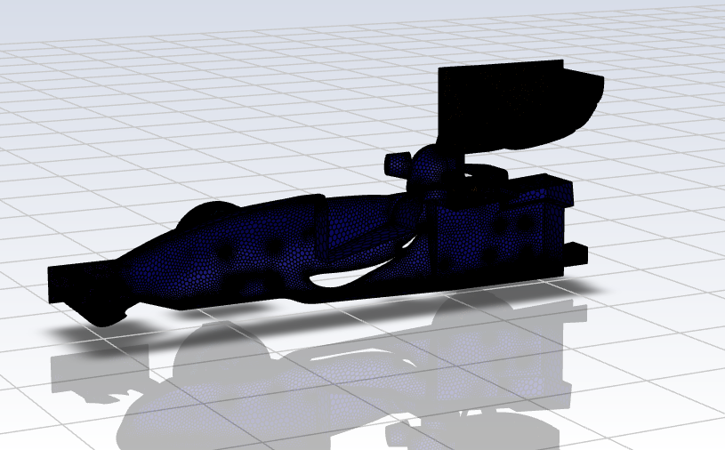
Looks like my mesh quality is good:
So it looks like wall/boundary condition is the issue?
Thanks again. -
June 18, 2025 at 8:05 amSubscriber
Can you share your input and output panels…
I do need to check velocity components. Again have checked your coordinatedsystem…?
-
-
-
June 18, 2025 at 8:07 amSubscriber
Wheel is rotating around X axis, your inputs are with respect to Z axis. Please just dont copy paste the steps, understand the procedures . Why we are doing them. You may have different inlet speeds , different tyre radius. Do your calculations
-
June 23, 2025 at 10:39 pmSubscriber
I thought I changed my wheels to rotate around X.
I have calculated different velocity speeds, for my tyre radius.
-
-
June 23, 2025 at 11:01 pmSubscriber
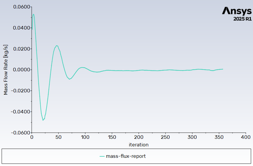
This is my first iteration's results:
Q1) How do they look?
Q2) For the Run sim results, how do I know if my half car CFD simulation results are for a half car, or full car model?Remembering that I have stated the Symmetry plane is Symmetry in Fluent Meshing, does Fluent Solution calculate that as half or full car model?
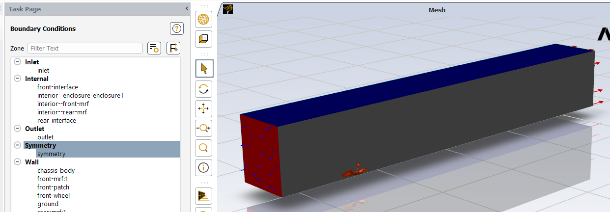
Inlet:
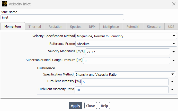
Outlet (default):
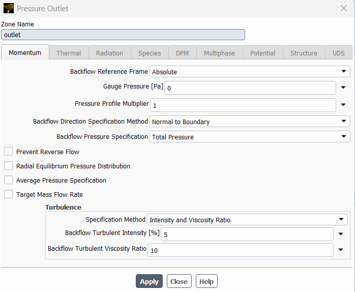
Thanks,
Kelvin
-
- You must be logged in to reply to this topic.


- JACOBI Convergence Issue in ANSYS AQWA
- Is it able to solve turbomachinery using density-based solver in Fluent?
- Two-way FSI simulation
- Ensight Force_per_unit area_EV
- RIBBON WINDOW DISAPPEARED
- Fluent Meshing Error when .dsco not .stp
- Ansys Fluent for modelling Ocean Wave reactions to Wave Barriers
- Battery Pack cooling
- ISAT ABORT error
- UNASSIGNED INTERFACE ZONE DETECTED FOR INTERFACE…

-
peteroznewman
 4597
4597 -
scabo
 1495
1495 -
Dennis Chen
 1386
1386 -
javat33489
 1209
1209 -
Shyam Prasad V Atri
1021


© 2025 Copyright ANSYS, Inc. All rights reserved.


