-
-
December 13, 2018 at 3:53 pm
BillT
SubscriberHello,
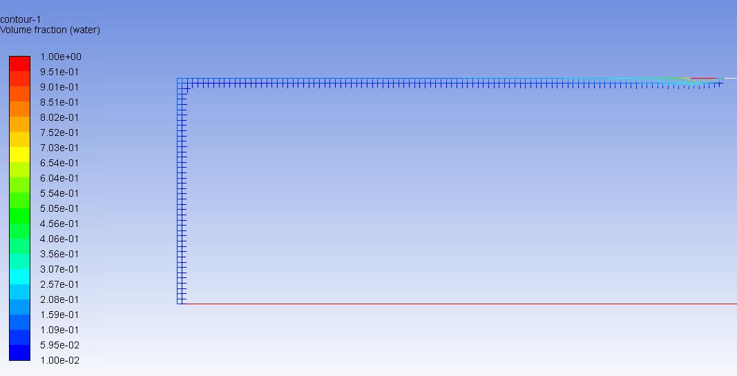
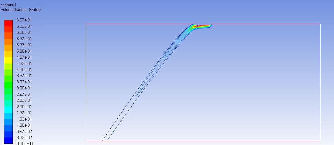
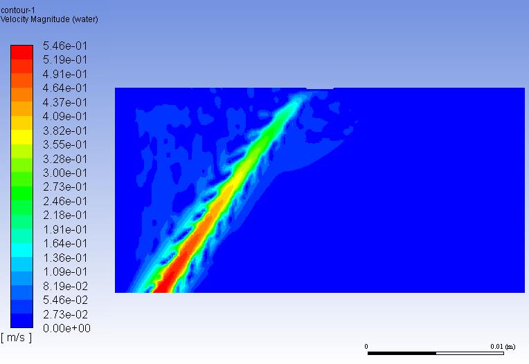
I am modeling a 2d multiphase flow (air and water) with gravity enabled in negative x- and y-direction. It seems that the water flows along the wall, even though the gravity is greater in y-direction (see below). The area is filled with air. Did I forget to disable any kind of wall adhesion? If I increase my velocity at the inlet, it doesn't flow along the wall.
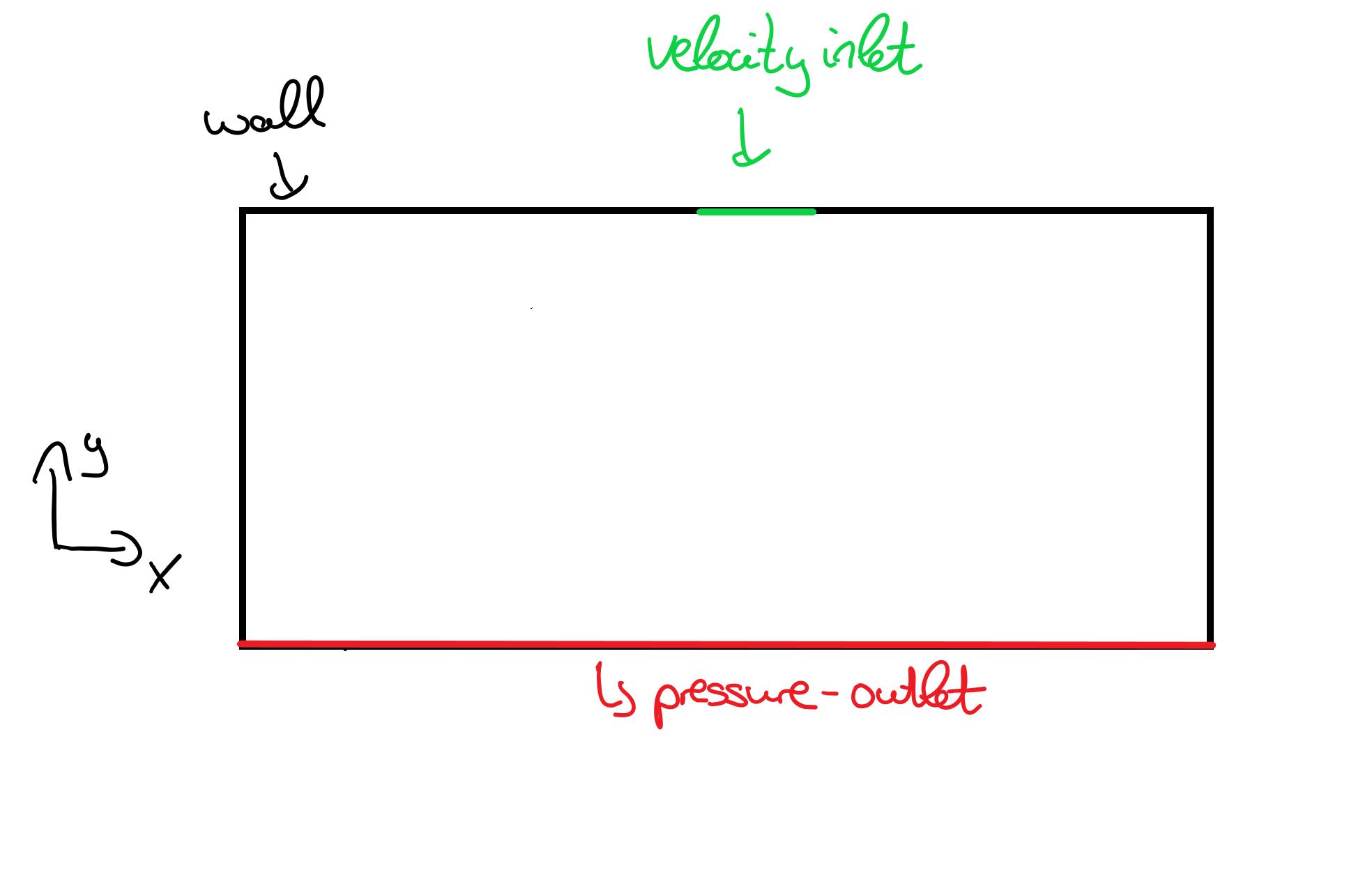
Some Boundary Conditions:
   Gravity: x: -4.25 m/s² ,    y: -7.3575 m/s²
  Velocity at inlet (Volume fraction of water = 1): -0.01 m/s
           Â
Thank you in advance!
Â
-
December 13, 2018 at 4:59 pm
Rob
Forum ModeratorPlease can you plot the phase contours & add them into the thread. I wonder if you've missed something in the boundary setting for the outlet, but equally it could be convergence so please also add the residual plot. Â
-
December 13, 2018 at 6:14 pm
-
December 13, 2018 at 8:14 pm
raul.raghav
SubscriberBillT, its still not clear where your different boundaries are located. Can you provide a detailed schematic which describes the different boundaries? Which is the inlet, outlet, wall? And provide a schematic of the coordinate system as well, so that we could understand the problem.
-
December 14, 2018 at 10:06 am
-
December 14, 2018 at 10:39 am
Amine Ben Hadj Ali
Ansys EmployeePlease paste a contour of Volume fraction (filled). From the first image one can (hardly) identify that water is flowing along the top wall in -X direction and then towards the -Y direction as it is expected if gravity is enabled and due to buoyancy. Just give proper operating density: give 0 kg/m^3 and set pressure outlet to the pressure outside the domain ( I think ambient).Â
-
December 15, 2018 at 1:04 pm
raul.raghav
SubscriberSomething seems to have gone wrong in your setup with the boundary conditions.Â
Could you attach your workbench archive file? Please follow these directions to upload a .wbpz file.
-
December 15, 2018 at 1:04 pm
BillT
SubscriberSorry for my late response. When I activate filled for the contour of my volume fraction it doesnt show any difference. But I set the range of water volume fraction from 0.01 to 1 (see below). How do I set pressure outside the domain to ambient? Shouldnt it be the same as setting the gauge pressure to zero?
-
December 16, 2018 at 2:43 pm
raul.raghav
SubscriberI looked at your files and everything looks fine to me. The -X direction gravity is high and the Y direction velocity is low, so what you're seeing in physically possible. I don't think there is anything wrong with the setup. However, there is one thing that you need to be careful about. There is reversed flow at the outlet and this could influence the results. I would extend the outlet such that it further away from the inlet. Then trying running the simulation again. Let us know how that goes.
-
December 17, 2018 at 10:28 am
BillT
SubscriberI appreciate that you looked at my files. When I put the outlet further away from my inlet it doesnt change the reversed flow issue. But I set the wall at the top of my boundary to pressure-outlet and it works fine.
Thank you for your help.
BillT
-
December 17, 2018 at 11:47 am
Rob
Forum ModeratorAs an aside, don't select any surfaces when plotting contours in 2d. You'll have much clearer graphics.Â
-
December 17, 2018 at 2:09 pm
raul.raghav
SubscriberOut of curiousity, can you attach a figure of the velocity or volume fraction contour after you set the top-wall to pressure-outlet?
-
December 17, 2018 at 2:40 pm
-
December 17, 2018 at 3:06 pm
Rob
Forum ModeratorYou've got a couple of problems here. The first is there isn't enough mesh to retain the water phase in the domain: it's diffusing out so your result won't be accurate. The second issue is that the air flow may be strong enough in 2d to deflect the water: can you plot (with filled contours) the velocity?
-
December 18, 2018 at 10:22 am
-
December 18, 2018 at 11:05 am
Rob
Forum ModeratorThanks. If you compare the mass fraction & velocity plots you're getting a very diffuse jet and that's causing problems with the numerics. Please can you adapt the region where the water is and continue the solution. You may need to do this a few times, so I'd also advise increasing the resolution on the original mesh: you're aiming for 10-15 cells across the water jet.Â
-
- The topic ‘flow along wall at small velocity’ is closed to new replies.
- How do I get my hands on Ansys Rocky DEM
- Unburnt Hydrocarbons contour in ANSYS FORTE for sector mesh
- Help: About the expression of turbulent viscosity in Realizable k-e model
- Script Error
- Facing trouble regarding setting up boundary conditions for SOEC Modeling
- convergence issue for transonic flow
- Running ANSYS Fluent on a HPC Cluster
- Point exception in erosion calculation
- Errors with multi-connected bodies using AQWA
-
1992
-
897
-
599
-
591
-
418
© 2025 Copyright ANSYS, Inc. All rights reserved.