-
-
March 12, 2020 at 9:38 am
myvue
SubscriberHello everyone,
I am a beginner in Ansys. My problem might seem very basic, but I have not been able to find a solution in older posts, so I hope someone would be kind enough to answer my doubts.
I am working on a concrete gridshell structure. In my first attempt, I tried to model the connections (nodes between the different "bar/rod elements") of the gridshell by bonded contact (edge to edge). The solution for total deformation showed that the connection between one of the parts fails and "swings like a pendulum".
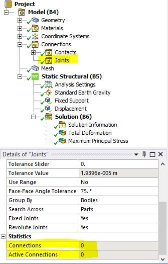
However, that is not what I wanted. I want the nodes in the structure to be rigid and remain fixed. So I tried adding fixed joints. I was having trouble 'automatically creating' joints (as I did for the contact elements) because in the joints tab, there is no option for edge-to-edge joints (the automatically created joints were not the edge to edge joints I wanted, but edge to face). So, after creating contacts as previously, I inserted the joints tab, but kept it empty. As can be seen from the picture below, the joints tab has '0 connections'.
I knew this was most probably wrong, but after the solution, I got the exact same result as before (same max/min deformation and position), except that this time, the connection of the part did not fail. It remained intact even though it had the same deformation and same principal stresses.
I want to know whether in the second attempt, joint connections were created in my structure replacing the contact elements (as I wanted)? If not, then why the change in results? If yes, then why the remaining results are exactly the same as before?
I would be extremely grateful for your reply. Thank you.
-
March 12, 2020 at 11:33 am
Aniket
Forum Moderator1. No there should not be any joints in your model,
2. there must be something else that causing changes in the results Easy way of checking that is to suppress the joints folder and resolving the same model again.
Instead of using bonded contacts between edge to edge, try using shared nodes for the beams if those joints are something that can be considered as bond or welded together. Search shared topology in the Ansys Help for more info.
-Aniket
Guidelines on the Student Community
-
March 12, 2020 at 11:34 am
Aniket
Forum ModeratorOne more thing it seems like you are looking at the results at auto scale. Please use true scale to actually see the results. or use the same scale to compare both results.
-
March 12, 2020 at 3:09 pm
myvue
SubscriberThank you Aniket for your reply.
I have performed the analysis of the above two cases seven or eight times by now, and I still cannot figure it out why I get a part suspended in one model, and not suspended in the other. As you suggested, I did suppress the joint and then cleared the solution and performed it again, this time I dont get the part hanging in the air. But by the same reasoning, when I apply a joint (an 'empty' one) on to a solution with bonded contacts (and a resulting suspended part), I get a solution that is not suspended anymore. I dont know which solution to believe or where I am going wrong. But in any case, why is that part suspended anyway? If we are saying that bonded contacts act like a 'glue', why does that part hang? Is it because the connection fails?
As for your other recommendation of shared topology, I performed shared topology in spaceclaim for my geometry. However, when I bring it to Ansys and try to mesh, after only a few seconds, an error appears: The mesher can not determine the endpoints for one or more edges.
And: Mesher failed to mesh topological edges.
I cannot even generate fixed joints. For my geometry, I would need to generate automatic joints, but the automatic joints that ansys generates are not edge-to-edge joints that I would like. I dont know how to obtain that? Any ideas?
-
March 12, 2020 at 3:11 pm
-
March 13, 2020 at 6:50 am
Aniket
Forum ModeratorDo a modal analysis first before going for a Structural analysis. This will tell you which contacts are working and which are not. You can also use contact tool to evaluate state of the contacts.
If you can not use Shared topology in SpaceClaim, try using node merge operations under the mesh edit folder.
https://ansyshelp.ansys.com/account/Secured?returnurl=/Views/Secured/corp/v195/wb_msh/gmsh_node_merge.html
For scale, you can see it as shown in the image below:
-Aniket
Guidelines on the Student Community
-
March 13, 2020 at 2:40 pm
myvue
SubscriberOh okay. So its the auto/true scale problem. The part is suspended (detached) in auto scale, but not in true scale. Why is that?
-
March 13, 2020 at 4:38 pm
Aniket
Forum Moderatorbecause autoscale uses exaggerated deformations by the factor shown (5 in the image that I inserted in previous reply).
Adding a blank folder or joints would not make any difference.
-
- The topic ‘Fixed Joints instead of Bonded Contacts, why the weird (similar but not similar) result?’ is closed to new replies.


-
4673
-
1565
-
1386
-
1231
-
1021

© 2025 Copyright ANSYS, Inc. All rights reserved.


