-
-
December 26, 2018 at 10:25 pm
Sam Fares
SubscriberHi All,
The angles below are 480 inches
1. How can i fix the edge of the fillet in yellow? as you can see it's not a smooth curve.
2. The angle on the left has some double vertical lines while the angle on the right his one single lines at the edges. Does this mean the angle thickness is not uniform in thickness thru its length? is there an easy to fix it?
Regards,
Sam
Â
-
December 27, 2018 at 2:20 am
peteroznewman
SubscriberHi Sam,
Use File > SpaceClaim Options, to increase the Rendering quality. This should improve the fillet.
If the double lines are still there after increasing the Rendering quality, please attach the .scdoc file.
If you are careful to make sure the Grid snap is appropriate, you will not get geometry errors like this.
Regards,
Peter -
December 27, 2018 at 3:09 pm
Sam Fares
SubscriberHi Peter,
Attached is the model. I created all the different contacts between the screws, wood and steel as you once described for me and i was able to analyze the model.
1. I realized I must've done something wrong with top chord angles. The top chord angle is 2x2x0.187 with an Area=0.7202 in2. The gap between the top chord angles is one inch. It appears it might be correct at one end of the joist but not the other. The gap at one end might be larger than the other. . All web meterials between the chord angles are one inch wide so the Top and bottom chord vertical leg should be touching them.i have been trying to fix the geometry but i wasn't successful. i hope its a simple fix.
2. Any suggestion to make the model mesh better, please feel free to modify it
3. this is suppose to be a simply supported truss. Is my modeling of this correct?
4. The truss Top Chord angles is suppose to be braced laterally( out of plane) every 36 inches,and Bottom chord angles braced laterally every 96 inches but without any restriction in the movement vertically . How do i do it?
Thank you for your assistance!
Regards,
Sam
-
December 27, 2018 at 3:49 pm
peteroznewman
SubscriberHi Sam,
One way to fix the bad geometry is to delete that component.
Select the two side faces of the Wood Nailer then create a Plane.
Click on the Mirror Tool, select the plane then select the good body.
The above edit causes some contacts in Mechanical to need repair.
If you could have just moved the faces into alignment, you wouldn't need to do any repair.
Perhaps instead of deleting, you could make the mirror body, then use the Pull tool on the crooked geometry with Up to button and select the face of the mirror body. Then you can delete the mirror body and none of the contact would need repair.
Please make those repairs and reply with a new model. I will look at the model for further suggestions.Â
Regards,
Peter -
December 28, 2018 at 10:50 pm
peteroznewman
SubscriberHi Sam,
3. this is suppose to be a simply supported truss. Is my modeling of this correct?
You show a fixed support on the welds on each end. This implies that the part that the seat is welded to is immovable. But that is not the case. The part the seat is welded to has flexibility. You could create a revolute joint to ground with the two weld faces and add a spring rate to represent the flexibility of the wall that the truss is welded to at one end. On the other end, it probably should have a general joint as there would not be any stiffness to prevent motion along the X-axis. So that would turn it into a roller-revolute type of constraint.
4. The truss Top Chord angles is suppose to be braced laterally( out of plane) every 36 inches,and Bottom chord angles braced laterally every 96 inches but without any restriction in the movement vertically . How do i do it?
You make sure there is an edge added to the angle every 96 inches and you add a remote displacement where all DOF are Free except for the lateral Y direction, which has a zero displacement.
Regards,
Peter -
December 31, 2018 at 9:53 pm
Sam Fares
SubscriberHi Peter,
Attached is the latest model. I have fixed the angles sizes and gaps.
For item 3 and 4 in the above reply:
3. Could you take a look at the revolute joints at both ends? How can make it better joints( pinned at left end and roller at right end). I'd like the pinned and roller joints to be 1 or 2 inch inward from each end.Â
4. The truss Top Chord angles is suppose to be braced laterally to prevent out of joist plane movement every 36 inches, but the top chord can move vertically. And Bottom Chord angles braced laterally every 96 inches but without any restriction in moving vertically. So bracing is for lateral stability. I am not sure how to do it as you described.
Any improvement to the model whether its a mesh or anything else would be appreciated!
Â
Regards,
Sam
-
January 1, 2019 at 2:47 am
peteroznewman
SubscriberHi Sam,
Happy New Year!
You could select an entity from each side to place the Coordinate System in the center on the the joint at each end.
For the Right End, I recommend a General Joint, not a Revolute, so there is no stiffness in the support along the X axis.
To provide lateral bracing on the angles, draw a curve on the edge of the angle, then use Split to divide the face in SpaceClaim to create a new edge between the blue and purple faces.
Then in Mechanical, add a Remote Displacement on that edge. Set Y to zero for lateral support, while leaving all other DOF Free.
You can use fewer elements if you use a Sweep Method on sweepable bodies.
The body on the right has a Sweep mesh control.
Best regards,
Peter -
January 2, 2019 at 4:51 pm
Sam Fares
SubscriberHi Peter,
Happy New Year!
Thank you for your reply. Attached is the latest model.Â
1. At the ends I tried to select an entity from each side to place the Coordinate System in the center on the the joint. It has worked at right end, but i wasn't able to do it at left end. Not sure why?
2. For Lateral Bracing, i drew a rectangle along the angle toe surface then i split the surface at 30" increment. i did it manual by moving along the surface and split the bigger surface at 30". Is there a faster way of telling Spaceclaim to split the surface evenly by providing the number of divisions? do i need to provide a thickness for this surface and material assignment?
3. Is the remote displacement is provided at the vertical edge of 30" increment? is there away to do the bracing in a group fashion at each location rather than individually?
i just updated the files after i wrote my previous questions.
4. Did i do the edges correctly for lateral bracing?
5. Do i need to provide a connection the curves or surface and the joist?
Â
Â
Beat regards,
Sam
-
January 2, 2019 at 6:41 pm
peteroznewman
SubscriberHi Sam,
1. Expand the Joint and select the Coordinate System under it then click on the Geometry line that says Click to Change and with the face filter, pick the two faces, then click Apply. The coordinate system will jump to the centroid of the faces.
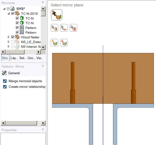
2. Draw a line on the face, create a linear pattern of that line along the face, use Projection to project all lines onto the face. See attached file. Its not a surface you are creating. You are making edges by breaking up one face of a solid into multiple faces.Â
3. Lateral bracing is only needed on one side or the other, not both since it is to prevent the whole structure from going sideways. If you are doing both sides you are over-constraining the structure.
You want a Remote Displacement on each edge, not one for all edges. All edges make a single point not go sideways and creates a spider of connection elements from that one point to all the edges. You want individual points on each edge that can't go sideways.
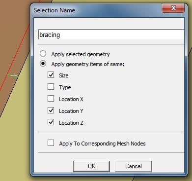
Make a Named Selection called bracing by clicking one edge then checking the Same Size, Y Location, Z location and it will find all 19 edges.
Create a Remote Displacement on one edge.
Use the Object Generator to automatically make the other 18 Remote Displacements.
5. I don't know what you mean. Maybe it's irrelevant due to the answers above?
Attached a new archive with Remote Displacements.
Regards,
Peter -
January 2, 2019 at 10:40 pm
Sam Fares
SubscriberThank you Peter!
1. What is the purpose of projecting all lines onto the surface?
2. i don't see these lines in spaceclaim any more. Is it because you projected them?
3. Since i don't see these lines, how did you pick the line to create the name selection?
4 Not sure what are these two nearly horizontal surfaces. i don't surfaces in spaceclaim but i see them in mechanical.
attached is the latest model
Regards,
Sam
-
January 3, 2019 at 1:17 am
peteroznewman
SubscriberHello Sam,
1. You project the lines onto the surface to create edges in the surface from the projection of the lines onto the surface.
2. The curves are hidden. You can click the checkmark next to the Curves folder and all the curves will be visible, but they are on top of the edges.
3. The post above showed operations in SpaceClaim. Once the solid geometry is attached to Mechanical, only faces and edges come over. No curves come over. In Mechanical you can select all edges of the same size and location.
4. I can't find any horizontal surfaces. I don't know what you have, but they are not in the file I downloaded.
 You have a lot of answers in this Discussion. It's time to start a new discussion if you have new questions.
Regards,
Peter -
January 3, 2019 at 2:51 pm
Sam Fares
SubscriberThanks a lot Peter!
-
- The topic ‘Fillet Fix, Double lines, Support, Lateral Bracing’ is closed to new replies.
- Unable to attach geometry 2024 R2
- Data Center Simulation
- DXF file loaded incorrectly
- Inventor 2025 files
- Ansys SpaceClaim and Discovery 2024 Facet shelling bug – 2022 version is better
- Masonry Brick Simulation
- Spaceclaim 2024 error FNE activation failed
- Simulating PCB
- How to do the snap fit insertion FEA?
-
1992
-
897
-
599
-
591
-
418
© 2025 Copyright ANSYS, Inc. All rights reserved.