-
-
July 12, 2023 at 4:44 pm
Jack Cool
SubscriberI have to do FEM anlalysis of aircraft frame. It consists of frame, rivets , skin panel.
It is only anlysis of inlet which means only loads that are in the inlet due to airflow will be considered. Skin on inlet portion is connected to frame using rivets. I have to find which rivets are in critical condition.
Following are the questions:
- What should be the boundary conditions. Should i use fixed support,remote displacement or displacement on aircraft frame outside.
- What should be the boudary condition on skin .eg I should apply elastic support on its sides since in reality it is constrained from side skin as well.
- What should be the contacts for rivets. (rivet head to skin, Rivet tail to frame , skin to frame , Rivet shanks to holes in skin and frame.
- Right now i am considering two loadings one is the Total pressure applied normally to aircraft skin. Wall shear stress in the direction of airflow to the skin. Is there any other boundary condition to consider.Thanks in advance.
-
July 13, 2023 at 1:22 pm
Aniket Chavan
Forum Moderator -
July 13, 2023 at 5:34 pm
wrbulat
Ansys EmployeeI'll share some of my thoughts, but (disclaimer) some of your questions constitute requests for engineering advice, which we are discouraged from providing. We can advise you on the appropriate program usage to mimic boundary conditions and applied loads that are, in your engineering judgement, applicable, but not on what assumptions to make (that's an engineering call, not a software one).
So... rivets and the skin in their immediate vicinity can fatigue. You of course want your modeling assumptions to represent the structural response with high fidelity, because these failures can be consequential:
Aloha Airlines Flight 243 - Wikipedia
Additional perspective... I witnessed (periferally) the development of a protoype capacitive sensor at the manufacturing systems technology lab at the University of Washington in Seattle (Prof Joe Garbini). A Boeing funded (of course) effort, it was used to quantify various aspects of geometric imperfections in the pre-drilled holes in aircraft skin that accept rivets. So, at least at the time, small imperfections in the rivet hole geometry were considered to be a possible contributing factor in fatigue failure.
We don't know the geometry of the portion of aircraft structure you are including in your model, and we certainly don't know that of the structure that extends beyond the boundaries of your model. But based on what I imagine it to look like, I offer you the following:
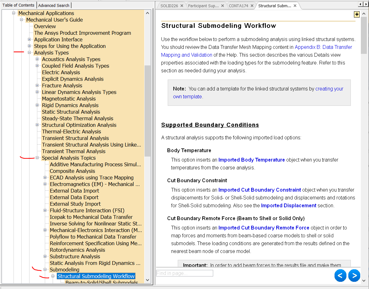
1 It is probably best, initially, to use force distributed (not rigid) remote points at the boundaries of your model. Actually, you might conduct an investigation... use a few different models truncated at different locations, and by trial and error determine what BCs on the cut boundaries of your smallest model most closely predict the stresses at the same locations in a larger one. This might help you establish most appropriate boundary conditions. Or you might consider submodeling:

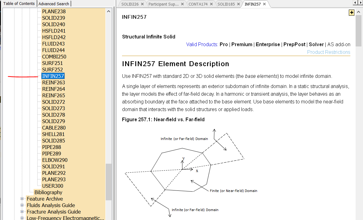
2. See my answer to (1) above. Also, you might consider trying a couple of features that are not natively exposed in Mechanical (and so would require the use of command objects to implement). These are (a) PML ("perfectly matched layers"):
and (b) the structural infinite boundary element (INFIN257):
The Help articles in the images above are in the Mechanical APDL Help. PML is probably easier to implement.
3. Probably best to use frictional contact anywhere there is contact between any of the rivet surfaces and those hole/skin surfaces that they contact. You might consider creating a localized detailed model of an individual rivet and the drilled material through which it passes. My guess is that the rivets are installed via some swaging process that causes plastic deformation, modest geometry changes, and might "press fit" the rivet shank against the hole through which it passes... a prestressed state that might be an important starting point for subsequent application of other external loads.
4. I was under the impression that the most deleterious loads are those associated with landing. I've heard (this is unsubstantiated) that, looking down the length of fuselages of commercial aircraft that have been in service for some time, one can easily see that these structures are no longer straight - permanent bends are brow-raisingly apparent. I remember hearing that this is a consequence of forces the structure is subjected to when landing. Ever experienced a hard landing? So my guess is that the external loads reaching a modeled portion of the aicraft structure can probably be treaded as quasi-static... applied (maybe) as nonzero remote displacements at the boundaries of your model. The response of the entire aircraft however is almost sure to be dynamic - landing forces probably encourage some natural frequencies to participate in the response. Submodeling again comes to mind...
Best wishes and have a safe flight.
--Bill
-
July 15, 2023 at 12:10 pm
Jack Cool
SubscriberThe outputs are Max stress in rivets.
How should i define boundary condition on skin.Since in actual aircraft it is connected to other portion of skin and is constrained to move in the direction of flow of air. I have modeled only that portion of skin which is connected to my frame not the entire portion if i apply pressure in direction of air which in my case is negative x_direction the skin will simply move in that direction it will not be contrained in x_direction. How should i constrain it in that direction so it accounts for the part that it is connected with other portion of skin. Should i use displacement boundary condtion.
Simiularly How should i constrain my frame. Should i use inertial relief boundary condition. Fix support or displacement in this case as well.
-
-
July 13, 2023 at 6:50 pm
Jack Cool
SubscriberThanks I'll work on your points and will reach you back.
-
- The topic ‘FEM analysis of aircraft frame/Bulkhead that includes rivets as well.’ is closed to new replies.


-
4999
-
1676
-
1387
-
1248
-
1021

© 2026 Copyright ANSYS, Inc. All rights reserved.


