TAGGED: static-structural
-
-
September 25, 2020 at 2:43 pm
ayodele1
SubscriberDear ANSYS,
I am carrying out an FEA study on a 6mm thickness, 1894mm diameter spade which is to be installed to blind/isolate an air line. The material of the spade is ASTM A36 and the air pressure is 1.37bara. The essence of my study is to determine the optimum thickness that could be safely used to blind or isolate the line. The inside diameter of the circular duct is 1830mm, while the below highlighted faces (front & back) of the spade will be tightened (i.e. enclosed) between flanges of the duct.
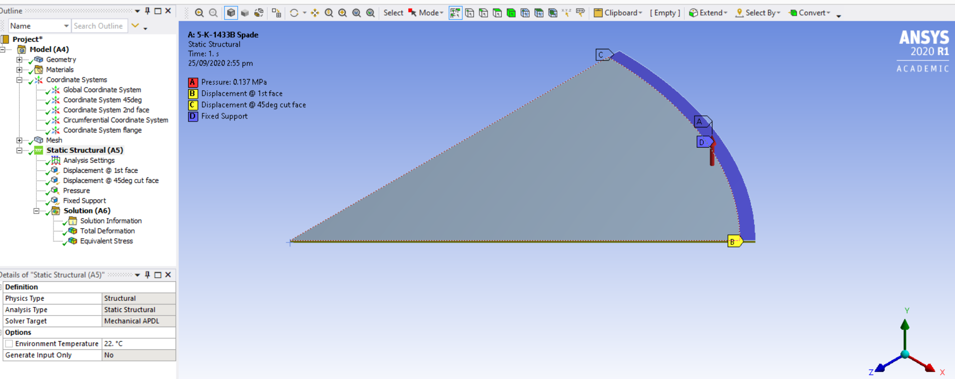
I have created below 45deg model of the spade in ANSYS SpaceClaim and set it up in ANSYS Mechanical. The geometry face in blue below was where I applied the "Fixed" support, while the face along the circumference will be resting on the flange bolts.
September 25, 2020 at 5:11 pmApril Wang
Ansys EmployeeHi Ayodele1,nThe general set up looks no problem too me. nRegarding the lager deformation than expected, you might want to check if the material is defined with correct unit.nAlso, shell element is recommended for this model. If you are using solid element, try use at least two layer of element along the thickness.nn nSeptember 25, 2020 at 7:24 pmSubscriberThanks Apwang.nI had actually entered the Modulus of Elasticity as 200,000MPa and the poissons ratio as 0.26 which are the material properties.nI am using solid element, and will use more layer of element as advised.nPlease any other ideas on how I may be able to obtain high fidelity result? nThanks in anticipation.nAyodele1nnSeptember 27, 2020 at 9:55 amSubscriberDear ANSYS,I am analyzing a 6mm thickness 1894mm diameter spade for fitness for blind-off service. The material of the spade is ASTM A36 and the load is air pressure @ 1.37bara. The inside diameter of the enclosing circular duct is 1830mm, while the faces D of the spade below will be fastened in the flanges of the duct. I created a 30degrees model of the spade and applied displacement (Symmetry) boundary conditions to the cut faces and fixed support to the fastening faces, as shown.n Figure 1:Boundary conditionsnn
 Figure 2:Equivalent StressnI have applied my pressure load on the free face of the plate as well as the fastened face, please is this set up correct?nThe maximum stress is concentrated at a point of one of the cut faces (as shown on above figure 2) and was the case through the mesh refinement. Please what could I be doing wrong as I expect that the stress concentration will be uniform across a radius close to the constrained face and not localized at a point?nI need help from anyone who can be of help.nMany thanks for your anticipated support.nAyodele1. n
Viewing 3 reply threads
Figure 2:Equivalent StressnI have applied my pressure load on the free face of the plate as well as the fastened face, please is this set up correct?nThe maximum stress is concentrated at a point of one of the cut faces (as shown on above figure 2) and was the case through the mesh refinement. Please what could I be doing wrong as I expect that the stress concentration will be uniform across a radius close to the constrained face and not localized at a point?nI need help from anyone who can be of help.nMany thanks for your anticipated support.nAyodele1. n
Viewing 3 reply threads- The topic ‘FEA of Spade Installed on an Air Line’ is closed to new replies.
Ansys Innovation Space Trending discussions
 Top Contributors
-
peteroznewman
 3597
3597 -
scabo
 1283
1283 -
Dennis Chen
 1117
1117 -
javat33489
 1068
1068 -
Shyam Prasad V Atri
983
Top Rated Tags
© 2025 Copyright ANSYS, Inc. All rights reserved.
Ansys does not support the usage of unauthorized Ansys software. Please visit www.ansys.com to obtain an official distribution.
-