TAGGED: ansys-mechanical, boundary-conditions, link, remote-displacement, remote-point, rigid, ship
-
-
November 1, 2024 at 10:32 am
mlefkiou
SubscriberHello,
Recently I am trying to implement a FEA according to Common Structural Rules (CSR) for Strength Assesment for a Bulk Carrier, using ANSYS 2024R2.
Currently, the geometry was created in Rhinoceros and was transferred then to ANSYS Spaceclaim. In Spaceclaim, the geometry in consisted of Shell & Beam elements for 3-dimensions, where the geometry model was succesfully created. The model can be seen below, which was opened in the ANSYS Workbench as Static Strucural Analsysis component and using ANSYS Mechanical: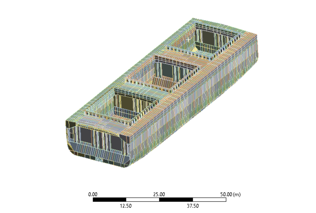
The Geometry then was opened in ANSYS Mechanical to implement the Meshing, the Loadings and the Boundary Conditions (BC) of the model.
1. For Meshing, the command Batch Connections was used to create the connectivity between the Shell & Beam elements of the structure. The mesh succesfully created.
2. For the Loadings, a Mapping was created through Python for the Dynamic Load Cases and Loading Condition I would examine with (X, Y, Z, Pressure) for each selected compartment / surface. These were brought in by the component of ANSYS Workbench External Data, which some CSV files were imported with the (X, Y, Z, Pressure). The Loadings were succesfully applied also.
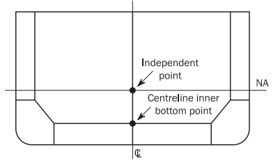
The issue seems to be with the Boundary Conditions. The CSR prescribe that the Boundary Conditions should be applied as follows:The points are given in the below image:
For the Cross Sections, Beams with the mechanical properties described in [2.5.4] were built, for both Aft & Fore End.
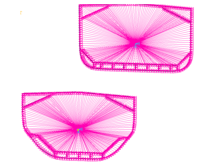
Currently I am struggling to apply the Boundary Conditions. I tried the Remote Displacement (by using Rigid behaviour) for each Independent point, but the analysis gives me warnings that there might be a rigid body displacement. Also the Intersection of centerline and the inner point displacement fixing was created.What I would like to achieve is the following connection:
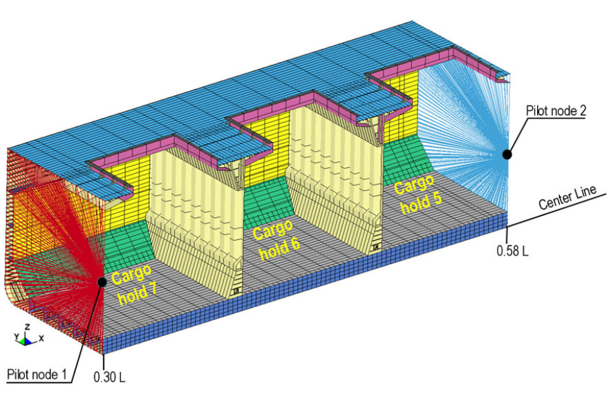
My question is, how I apply properly the above Boundary Conditions, though ANSYS' environment? Do I need to insert a Remote Point, use Remote Displacement or something different than these?
Thank you. -
November 2, 2024 at 12:53 am
peteroznewman
SubscriberUse Remote Displacement, behavior = Rigid at the Fore end and another one at the Aft end.
On the Aft end, promote to a Remote Point so you can use that to apply the Moment load.
Use a Remote Displacement at the intersection of centerline and bottom to set X=0 leaving the others Free, though I don't see why you wouldn't simply add X=0 to the Fore end Remote Displacement instead of leaving that free and making this separate Remote Displacement.
Ignore the warning about rigid body motion. These three Remote Displacements provide the correct six constraints to prevent rigid body motion.
-
November 5, 2024 at 9:01 pm
Reza
SubscriberHello, I want to define different pressures for each X, Y and Z along the hull of the ship, but External Data does not seem to consider each coordinate separately. How can I select the hull shell as a body and import pressures on each X, Y and Z? Thank you,-
November 6, 2024 at 7:14 am
mlefkiou
SubscriberHello, in order to define the different pressures for each (X, Y, Z) Coordinate you will need to do the following:
- Define in an Excel file the 4 columns with X, Y, Z and Pressure
- Convert it into a CSV file
- Import it through External Data
- Make sure to fill the row which the CSV will be imported, meaning the field Start Import At Line. i.e. if you have a row of Headings, then Start Import At Line = 2
- Fill in the Data Type & Units for each column in External Data from Table of File, for columns A, B, C and D.
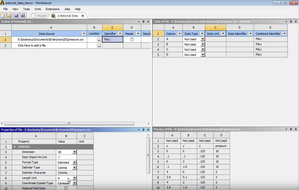
- Re-read the data files to the Project
- By going next in ANSYS Mechanical you will see Imported Load in tree-grid structure
- Import a pressure load by right-click on Imported Load, then Insert and then selecting Pressure
- Then you will the define the Geometry in the Pressure load

- Select the Geometry
- Then right-click on the Pressure load and select Import Load
I am not sure if I answered your question.
-
November 6, 2024 at 7:01 pm
Reza
SubscriberI appreciate your time and detailed explanation. I tried all those steps before, but it seems Mechanical does not accept more than a certain number of points. I have about 190,000 points on the hull. Another way to decrease the points, is to divide the hull into 25 sections or so.
-
November 7, 2024 at 8:45 am
mlefkiou
SubscriberHello,
190,000 points are a lot and would not be needed.
ANSYS Mechanical "interpolates" values of pressure between the points you import, so it creates a pressure distribution in all the surface you require to apply this pressure load.
Try to define in some certain areas and boundaries the values of pressure for some points. I would suggest give the (X, Y, Z, Pressure) for around 1000 points in the outter surface for a 300 meters ship would be definitely enough.
-
-
- You must be logged in to reply to this topic.


-
4633
-
1535
-
1386
-
1225
-
1021

© 2025 Copyright ANSYS, Inc. All rights reserved.

