General Mechanical

General Mechanical

Topics related to Mechanical Enterprise, Motion, Additive Print and more.

Fatigue Analysis

    • venkata sai prakash koppisetti
      Subscriber

      I was posed with a problem where I were to apply loading conditons as shown in the figure and get the fatigue life of the specimens, but how to apply these loading conditions?  

    • peteroznewman
      Subscriber

      What material are you using?  Does that material have a S-N Curve?

      For example, the Structural Steel that is automatically assigned to every model has an S-N Curve that is shown below.

      The table shows the S-N curve for an Alternating Stress with 0 Mean Stress. Case (a) shows a cycle that goes from 0 to 650 MPa, so the Mean Stress is 325 MPa and the Alternating Stress is 325 MPa.

      You could either do hand calculations using fatigue equations, or you could use the Ansys Fatigue Tool. What do you want to do?

      If you want to use the Ansys Fatigue Tool, you need to apply a Force to the model that creates the nominal stress of S = 650 MPa.  Use the equation S = F/A where F is the force in Newtons, and A is the area in square meters and S is the stress in Pa. The area A is the width of the narrow center times the thickness of the material, where units are in meters.


    • venkata sai prakash koppisetti
      Subscriber

      Thank you peter for your reply. I do have S-N Curve details.

      I would like to use fatigue tool. As you can see the stress varies from 650 MPa to 0, so do i need to create a table for force application? or constant force which results in 650 MPa stress generation needs to be applied in static structural?

      In case (a) you referred to mean stress as 325 MPa, So, is this an input that goes along with S-N

      curve data in the engineering data?


      Aslo, if I enter the value of mean stress of 350 MPa in Engineering data, Which option from fatigue tool should I select? Would that be a zero based or fully reveresed?                                                                        

      I have selected the life unit as seconds and one cycle as 2 seconds. Am I correctly representing the cylce?


      Thanks in advance.

    • peteroznewman
      Subscriber

      Apply a Force to the model that creates the nominal stress of S = 650 MPa.  Use the equation S = F/A where F is the force in newtons, and A is the area in square meters and S is the stress in Pa. The area A is the width of the narrow center times the thickness of the material, where units are in meters.

      Use the Fatige tool with a value of R = 0 which means it cycles between 0 and 650 MPa.

      Use your S-N curve data which was collected with an R = -1 value for fully reversed loading or a Mean Stress = 0.

      Use a Mean Stress Correction in the Fatigue tool to correct for the fact that you don’t have an S-N curve for your mean stress of 325 MPa.

      Your cycle time is 2 seconds, so you can get life calculated in seconds.

    • venkata sai prakash koppisetti
      Subscriber

      Just to confirm "R" is Scaling factor right?

      "Use a Mean Stress Correction in the Fatigue tool to correct for the fact that you don't have an S-N curve for your mean stress of 325 MPa." - can you eloborate this?

    • venkata sai prakash koppisetti
      Subscriber

      Do I need to enter 325 MPa as mean stress in Engineering data beside SN curve data?


    • peteroznewman
      Subscriber

      No, R is not the Scaling factor.  R is the stress ratio = Min_Stress/Max_Stress  In the details window, the Type can be Fully Reversed which is an R = -1 and was the type of loading for the S-N curve, or the Type can be Zero-Based, which is an R = 0 and is the type of loading for your problem.  The scale factor for Case (a) is 1.0 if you apply the force that creates 650 MPa of stress.

      You will use a different scale factor for Case (b).

    • venkata sai prakash koppisetti
      Subscriber

      What was the Mean Stress Correction in the Fatigue tool you were talking about earlier?

    • peteroznewman
      Subscriber

      Choose a Mean Stress Theory such as: Gerber, Goodman, Soderberg, etc. instead of using None.

    • venkata sai prakash koppisetti
      Subscriber


      The cross section area was 16 mm2, so to generate 650 MPa stress, I applied 10400 N force but it resulted in 750 MPa stress, so I reduced the force applied to 9400 N which resulted in equivalent stress of 652 MPa.  

      .


      But the equivalent alternating stress under fatigue is around 1120 MPa, but as you said isn't this supposed to be 325 MPa?  Also there is an warning as shown below.


    • venkata sai prakash koppisetti
      Subscriber


    • peteroznewman
      Subscriber

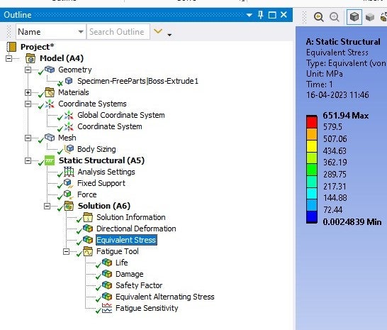
      The force you calculated is to get an Engineering Stress of 650 MPa.  Ansys calculates True Stress, which is why you got a value of 750 MPa.  For small values of strain, Engineering Stress and True Stress are almost equal.  Perhaps the curved sides of this geometry is creating a stress concentration that cuases the engineering stress to rise slightly.

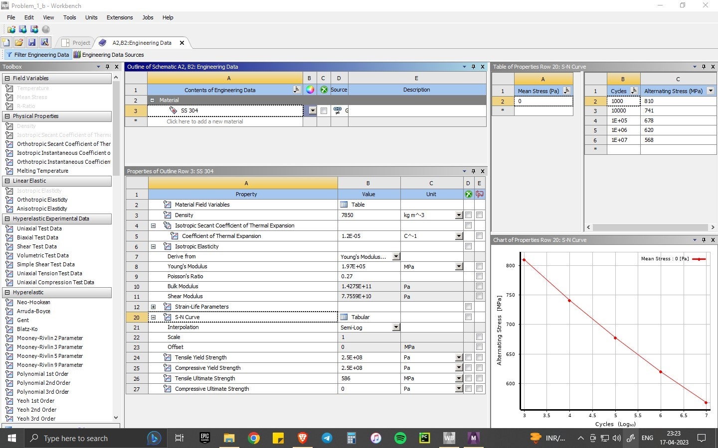
      The warning is very useful because fatigue calculations using an S-N curve are valid when equivalent stress is less than yield strength. This is also called high-cycle fatigue.  When stress is greater than yield strength, different fatigue calculations use strain-life equations. This is also called low-cycle fatigue. Please show the material properties.  What is the UTS?

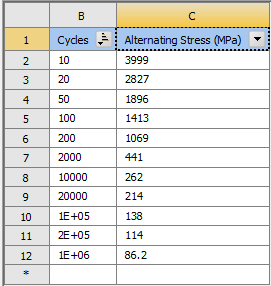
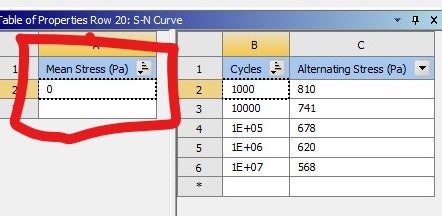
      Do you have a textbook that has a good chapter on Fatigue?  I recommend Mechanical Behavior of Materials: Engineering Methods for Deformation, Fracture, and Fatigue by Norman E. Dowling. This will show you how to do Fatigue hand calculations using equations and S-N data. I suggest you first complete case (a) using the textbook equations.

      Have you read the Ansys Help on the Fatigue Tool?  Here is the URL:
      https://ansyshelp.ansys.com/account/secured?returnurl=/Views/Secured/corp/v231/en/wb_sim/ds_Fatigue_Overview.html
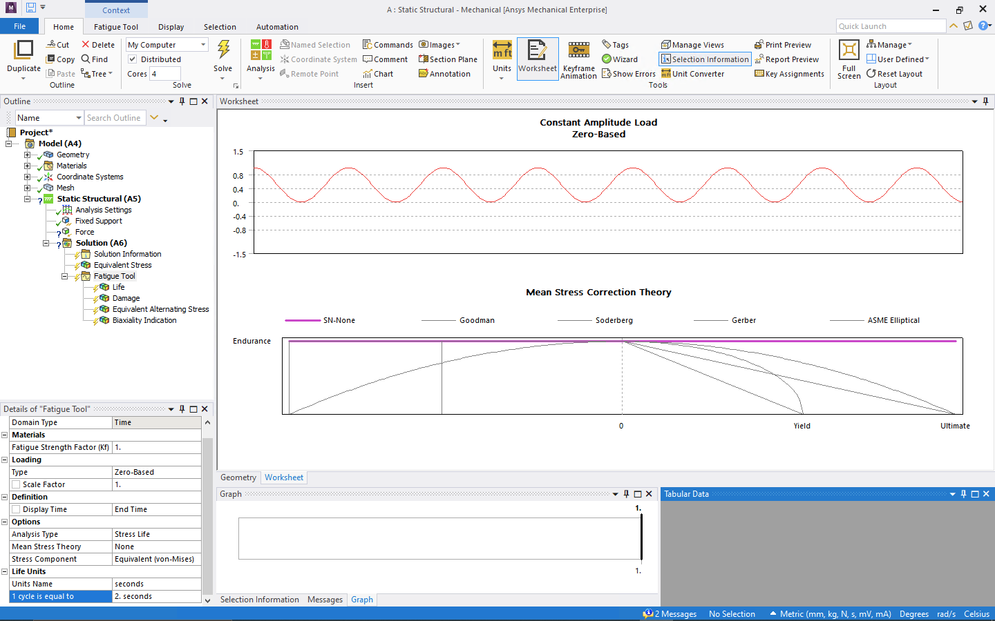
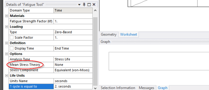
      Click the Help menu in Workbench to open Ansys Workbench Help, then copy/paste the above URL into the browser address bar. This will help you to understand what the Fatigue Tool is doing. Then you can complete case (a) using the Fatigue Tool and see if you get the same answer.

    • venkata sai prakash koppisetti
      Subscriber

      In case a and b the loading is step loading, I think the loading you suggesed would give me cyclic loading. How to give step loading input?

    • peteroznewman
      Subscriber

      Ansys takes the state of stress at the end of the analysis to do the fatigue calculations. It doesn't matter if the load was ramped on from t=0 to t=1 or applied as a step load.

      • venkata sai prakash koppisetti
        Subscriber

        In case (b) I am not able to get satisfactory results from the loading. I applied loading as suggested ( ratio loading with R as 0.1) but am facing the same errors

    • venkata sai prakash koppisetti
      Subscriber

    • peteroznewman
      Subscriber

      Delete the Compressive Ultimate Strength of 0 and the Warning message might go away.

    • venkata sai prakash koppisetti
      Subscriber

      Deleted it, but did'nt help. Could there be problem in the way I am applying loading? I gave a displacement of 0.23 mm which gave an equivalent stress of 998 MPa. But somehow the alternating stress for this is around 7000 MPa.

    • peteroznewman
      Subscriber

      How did case (a) turn out?   Did you do a hand calculation?  What was the result?  Did the Fatigue Tool give the same result?

Viewing 17 reply threads
  • The topic ‘Fatigue Analysis’ is closed to new replies.