TAGGED: farfieldspherical, fdtd, lumerical
-
-
June 23, 2023 at 8:33 pm
sagar
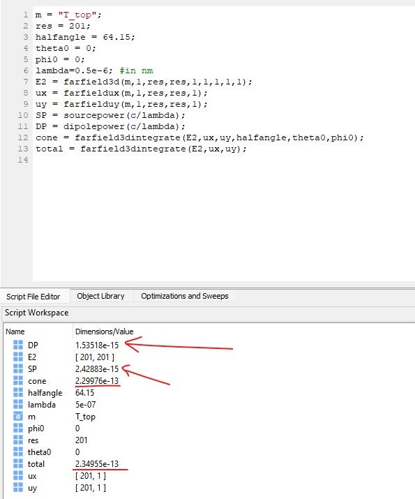
SubscriberI did far-field integration for the monitor placed on top of the structure, and the dipole placed inside the structure and calculated how much power flowed through the power monitor for one wavelength and integrated power over half-angle 64 degrees. Also calculated dipole power and source power for the particular wavelength.
Here is the picture of the script I have used and the calculated values:
How can the integrated far-field power be more than source power or dipole power?
My goal is to calculate the percentage of the total emitted power of the dipole is flowing at a solid angle in the forward direction.
-
June 26, 2023 at 6:24 pm
Guilin Sun
Ansys EmployeePlease note that the integrated E2 is not the power. It has coefficients that are missed to get the power. Please check the power formula.
-
June 26, 2023 at 8:09 pm
sagar
SubscriberOkay got it. But in both cases, the total and cone a constant factor will be multiplied. I have followed the formula suggested here: https://optics.ansys.com/hc/en-us/articles/360034914813-Integrating-power-in-far-field-projections
Where the far field fraction is taken by the integration of E2 in a solid angle by E2 in the hemisphere, and then by multiplying this factor by transmission we can get the fraction of source power transmitted into the far field within some solid angle. I think what I have done is correct then. Thank you.
-
June 26, 2023 at 8:15 pm
sagar
SubscriberI the website it is mentioned
Power norm = far field fraction * near field power transmission.
So, to get near field power transmission by a monitor, how far monitor should be placed from the structures? I have placed the monitor 1.2 um (twice the wavelength) from the structures. Is it okay?
-
June 26, 2023 at 8:42 pm
sagar
SubscriberI have checked by placing the monitor at different distances from the structure, where an electrical dipole was placed inside the structure and observed a significant change in Transmission, where I am not using any absorbing medium, so the power propagating through the different positions after the structure should be same as there is only air just after my design. Why are the changes happening even with slight movement in the monitor position?
-
June 26, 2023 at 11:18 pm
Guilin Sun
Ansys Employee1: this webiste https://optics.ansys.com/hc/en-us/articles/360034914813-Integrating-power-in-far-field-projections is correct for calculation the power in the farfield.
2: usually you do not need to place the monitor far away to be twice the wavelength, except you simulate larger volume. For better accuracy the monitor can be closer in general
3: for a dipole source, if you only use one planar monitor instead of a box, it is understandable that the further away the monitor, the smaller the power it records, as it cannot pick up the power with larger radiaiton angles. Thus, to get better result, the monitor should be closer, and the simulaiton area along the monitor should be large enough and the monitor edge should have almost zero intensity. It can be very challenge when a dipole radiates in -90 to 90 deg, eg, the strongest radiation is along the monitor surface. This is related to dipole polarization.
-
- The topic ‘Farfield power integration value is larger than source power’ is closed to new replies.


-
4683
-
1565
-
1386
-
1242
-
1021

© 2025 Copyright ANSYS, Inc. All rights reserved.


