We have an exciting announcement about badges coming in May 2025. Until then, we will temporarily stop issuing new badges for course completions and certifications. However, all completions will be recorded and fulfilled after May 2025.
General Mechanical

General Mechanical

Topics related to Mechanical Enterprise, Motion, Additive Print and more.

Failed to Generate the rotation of masses

    • de.serrano
      Subscriber

      Hello,

      I have tried several times to analyze the influence of force 3 (E) on the contact force between the masses (brown and green) and a part of the system. I define this contact as frictionless, which allows separation and sliding. In addition, I deactivated the option for small sliding in the contact and activated the option for large deformations in the analysis. I have tried different combinations in the other contacts, between 'Bonded' and 'No separation' type contacts, as well as defining revolution type joints between some parts. However, none of this has worked, as it seems that the motion is not being transmitted or the masses are not able to slide. I would appreciate any help, as I have exhausted every possible configuration I can think of.

    • peteroznewman
      Subscriber

      Hello Daniel,

      Explain in more detail how these solid bodies are connected in reality. Show each inseparable assembly.  Show where those assemblies make contact with each other that allows separation and sliding. I see you have Forces C and D that point at each other. Are those supposed to represent some kind of nut and bolt that pulls those two holes toward each other? 

      • de.serrano
        Subscriber

        Hi Peter,

        Thank you for replying. This sub assembly (ESM 1) is fixed:


        On the other hand, this is the sub assembly (ESM 2) which has rotation about Z. 

        The contacts between the components of ESM 1 are defined as 'Bonded' and the contacts between the components of ESM 2 are also defined as bonded (I also made another configuration defining them as Rev Joints). The contacts between ESM 2 components that come in contact with ESM 1 are set to 'Frictionless'.  Regarding the Forces C and D these are to represent the effect of compression springs.

        Regarding the contacts. These are the contacts that should allow sliding and separation:

        and this contact should allow sliding but not separation:


    • peteroznewman
      Subscriber

      What is the other end of the compression spring pushing against?  Is there a “ground” that is not modeled that the other end of the compression spring pushes against? Force D is on a rotating part. Is the other end of that compression spring also rotating?

      The title of this discussion is about rotation. What axis are you talking about for rotation? Is it the central axle that is along the Z axis?  You don’t have any load that causes rotation about that axis. You have Force E which seems to pass through the central axis.  Force E could produce some small deformation of the central axis by bending, but I don’t think that is what you are interested in.

      In the new images, I see a lever off the central axis. If you were to apply a Remote Displacement to the hole in the lever and set the X component to -5 mm leaving the other components Free, then you should see the rotating assembly rotate.

      • de.serrano
        Subscriber

        Hi Peter,

        I am sorry if my explanations have not been clear. First of all, with respect to the forces D and C these are to represent the effect of a screw spring system that are located in those holes.

        Regarding the rotation of ESM2, it is correct the rotation is with respect to the central axis of that subsystem which is aligned with the Z axis of the coordinate system.

        The force E is applied on the lever hole in the X direction to generate a moment and thus generate the rotation of the system.

        The objective of the simulation is to estimate the minimum force E to overcome the contact force in the zones of interest (images above) using Direct Optimization. With respect to the remote displacement I also tried applying it to the lever or even directly to the masses.

    • peteroznewman
      Subscriber

      Hi Daniel,

      Thank you for those extra details, now I understand how the mechanism is supposed to operate.

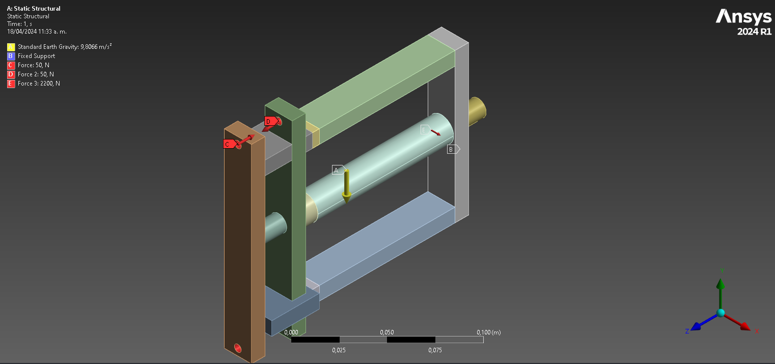
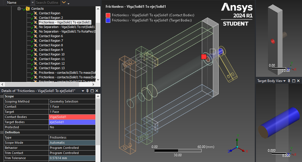
      It would be best to create a coordinate system that has a direction normal to the lever to use with a Remote Displacement on the hole in the lever. In a Static Structural model, it is much easier to solve with a displacement input than a force input, especially when there is friction and the mechanism is initially sticking and then breaks free. Request a Probe on the Reaction Force of the Remote Displacement to show the force vs time.  Use a small displacement of the lever.  Under Analysis Settings, turn on Auto TIme Stepping and set the Initial and Minimum Substeps to 30 and the Maximum Substeps to 3000.  That will guarantee you get at least 30 points on the Force-Displacement plot.

      If you don't get this working, use File Archive to create a .wbpz file and upload that (not the .wbpj file) to a file sharing site such as Google Drive, OneDrive or Jumpshare. If you use Google, make sure that you choose to allow anyone with the link to download the file. I will take a look at your model.

      • de.serrano
        Subscriber
        Hello Peter,
         
        Again thank you very much for taking the time to help me. During the day I made the changes according to what you indicated and additionally tried it with different settings in the contacts (which is where I think the problem is). However, I could not get the rotation of the lever to be transmitted to the masses. Attached I send you the link with the .wbpz file.
         
        Thanks again.
    • peteroznewman
      Subscriber

      Hello Daniel, success!

      I made one important change, and that was to replace this Frictionless contact with a cylindrical joint. 

      The reason that change is important can most easily be understood when meshing with a very coarse mesh, which I was forced to do because I was solving on the Student license that has a node count limit. Look at the brown pin in the hole in the gray part. It looks like an Allen wrench in a socket head cap screw. It does not allow rotation. By replacing Frictionless contact with a Cylindrical Joint, the pin is free to rotate in the hole.


      Link to Archive

      • de.serrano
        Subscriber
        Hello Peter,
         
        I have already checked the file you attached. Thank you very much for your help!
Viewing 4 reply threads
  • The topic ‘Failed to Generate the rotation of masses’ is closed to new replies.