You can continue an analysis from a previous one using the deformed geometry and "External Data" to read in initial stress or strain state. Theoretically, you should be also able to apply a displacement load to the undeformed geometry, as we do in a substructure analysis at the interface, but the technical issue is that Ansys doesn't allow the displacement import from "External Data" as an initial condition. Only the stress and strain can be applied as an initial constraint, and you should apply one or the other, but not both, since that is an unnecessary overconstraint.
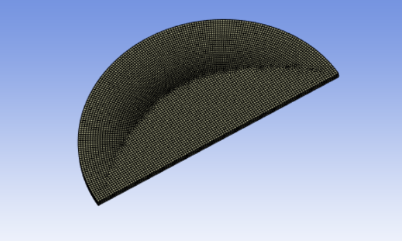
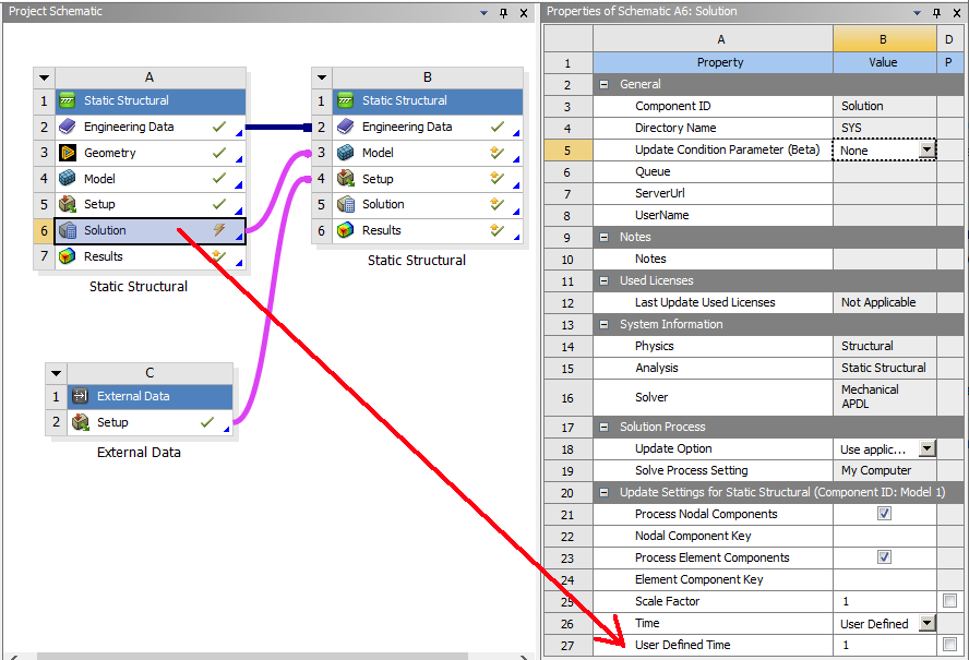
To transfer the deformed model, one method is to link Solution cell to Model cell. You will also link an "External Data" to the downstream "Setup cell":
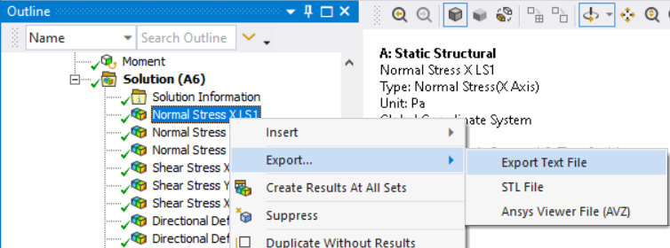
In the upstream model, you right click on the 3 X, Y, Z normal stresses and 3 XY, YZ, XZ shear stress to "Export Text File":
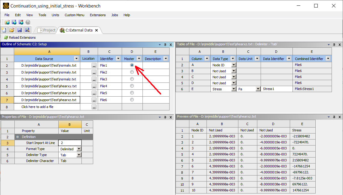
In the External Data system, one file must be marked as Master:
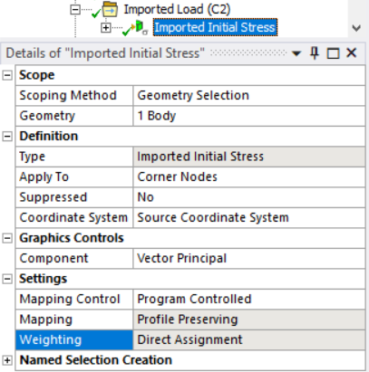
When Solution cell is linked to Model cell to transform deformed geometry, the initial stress import “Weighting” only accepts "direct assignment" import no matter whether “Mapping Control” is set to “Program Controlled” or “Manual.” This matches up data at node IDs, so you must only tag the node Id column and stress value column.
When deformed data is transferred through an unlinked method, such as through STL, pmdb, cdb, you will be able to set mapping methods, instead of direct assignment, and you must specify the X,Y,Z locations column in the "External Data." You will need to use a command snippet to export the 6 stress components at the deformed locations.
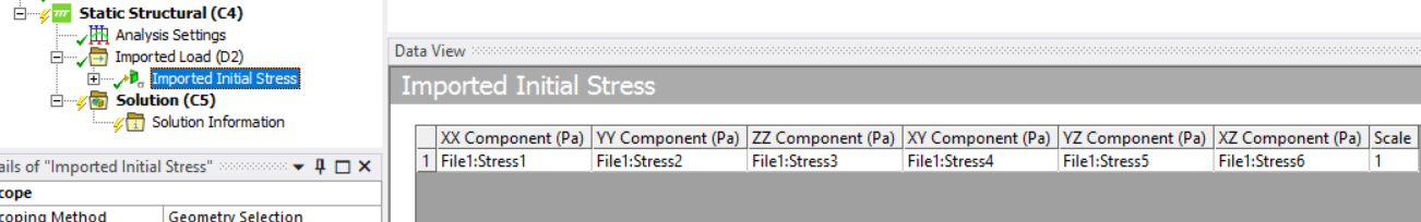
In the “Imported Initial Stress” in Mechanical you must set the 6 columns:
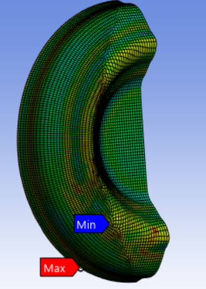
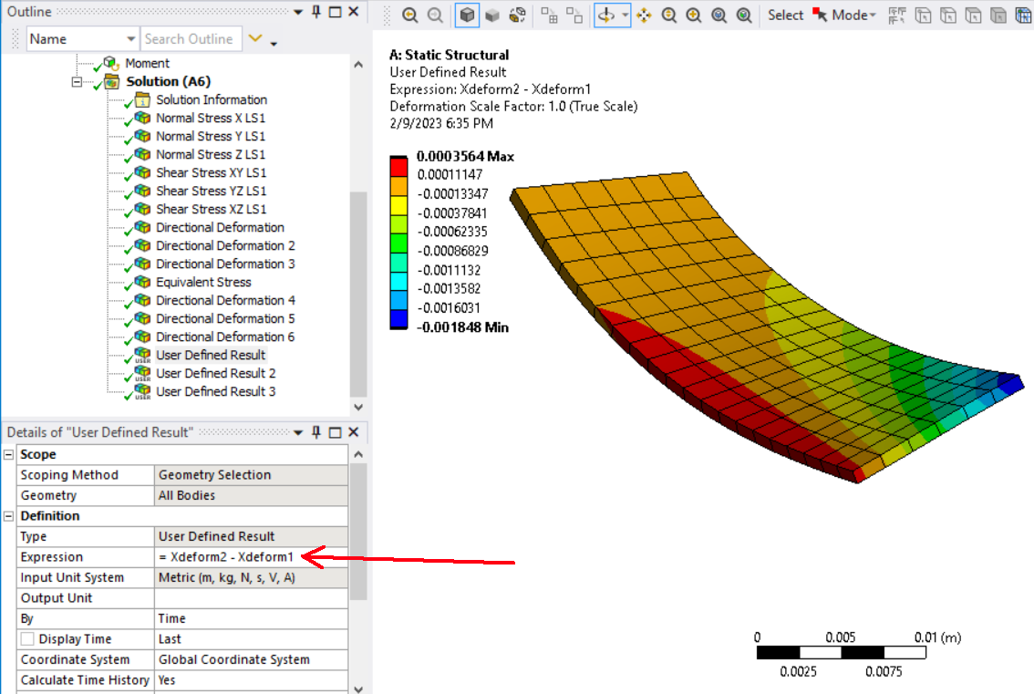
To compare the deformations in the first analysis to the second, You could use User Defined Results (UDRs) to subtract the deformation in load step one from the deformations in load step 2:
You can directly compare the stresses at the end times without any subtraction.
You could have just exported one “Vector Principal Stress” result from Mechanical instead of the 6 stress components if “File > Options > Export > Show Tensor Components” is on. Video at:
https://www.youtube.com/watch?v=aAnSv7r7EnM