TAGGED: ansys-mechanical, meshing
-
-
December 2, 2021 at 9:24 pm
NimaNZ
SubscriberHi everyone
In ansys ICEM when we produce a structured mesh using blocking techniques, at the end the mesh will be exported as an unstructured mesh to remove all those blocks and it will be an integrated mesh. All those extra surfaces due to blocking will be removed.
Could you please let me know if there is the same commands in ansys mechanical? Because when I export the mesh from mechanical it will be a mess inside the fluent.
Cheers!
December 3, 2021 at 5:07 amKeyur Kanade
Ansys EmployeeAs far as I know there is no such command in Ansys Mechanical.
Can you please insert some images to explain mess inside Fluent.
Please go through help manual for more details
Regards Keyur
How to access Ansys Online Help Document
Guidelines on the Student Community
December 3, 2021 at 11:54 amNimaNZ
SubscriberThank you for your response. I also could not find anything like that. The mess is the domain has been divided into multiple blocks but there is no command to integrate all those together after meshing as per ICEM.
December 3, 2021 at 1:40 pmRob
Forum ModeratorYou mean Ansys Meshing, not Mechanical. To avoid all the stray surfaces use a single Named Selection on the many fluid volumes.
December 6, 2021 at 4:12 pmNimaNZ
SubscriberThank you for your reply. Yes, my apologies, I meant ANSYS meshing. I changed the names of sub-domains to the same name but that doesn't make any difference; I found the blocking method for structured mesh at the end should be exported as an unstructured mesh to provide neat boundary conditions. For bluff bodies, I used ICEM for meshing and blocking and that's easy, but once there is a window, defining the building thickness in ICEM is tricky. Should you have any tutorials related to this I would be grateful to have it.
December 7, 2021 at 11:29 amRob
Forum ModeratorCan you post an image of the boundary list? That may help see what/if the problem is.
Unless you really want to mesh the building thickness you don't. In Fluent for thermal models we can assign a wall thickness for conduction modelling: read up on the wall options in the Fluent User's Guide and specifically "coupled" walls.
December 7, 2021 at 2:03 pmNimaNZ
Subscriber
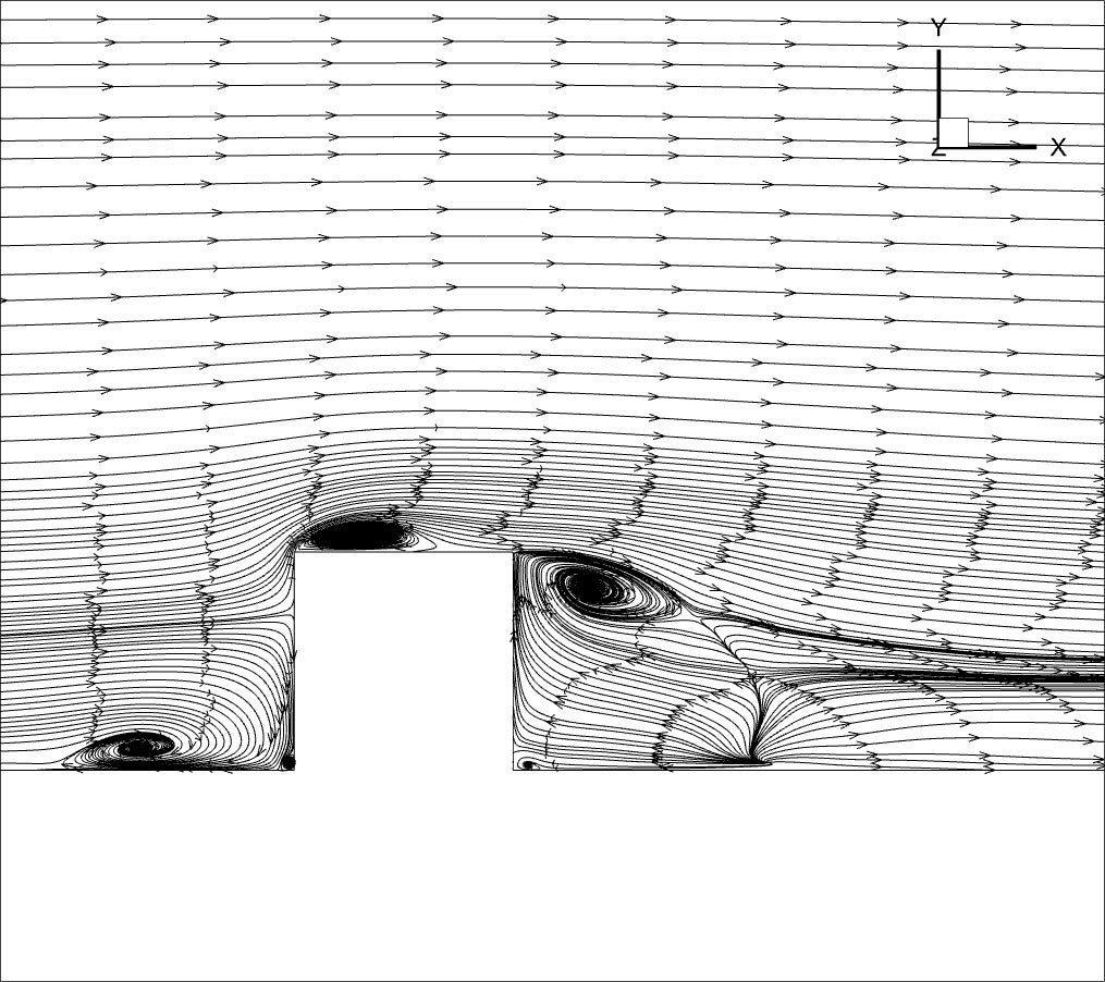
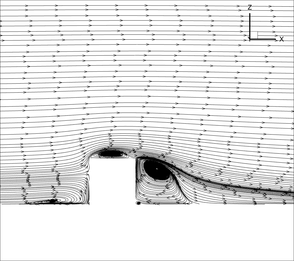
The boundary list is correct, and it is uniform. But after struggling with many cases I realized there should be something wrong with the mesh. Then I ran a case with GAMBIT mesh, the streamlines show correct flow structures, however, the mesh generated by Ansys meshing doesn't give the correct flow structures. The mesh generated by ICEM CFD seems perfect as it gives the minimum orthogonality of 1 and the boundaries are uniform.
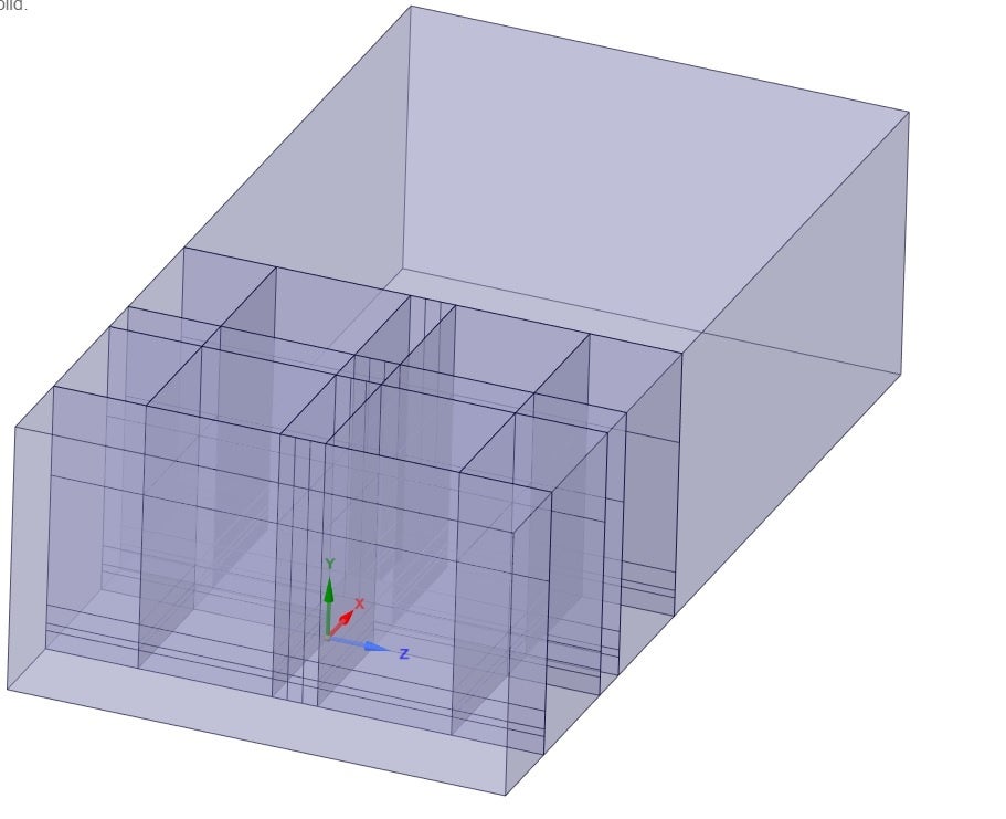
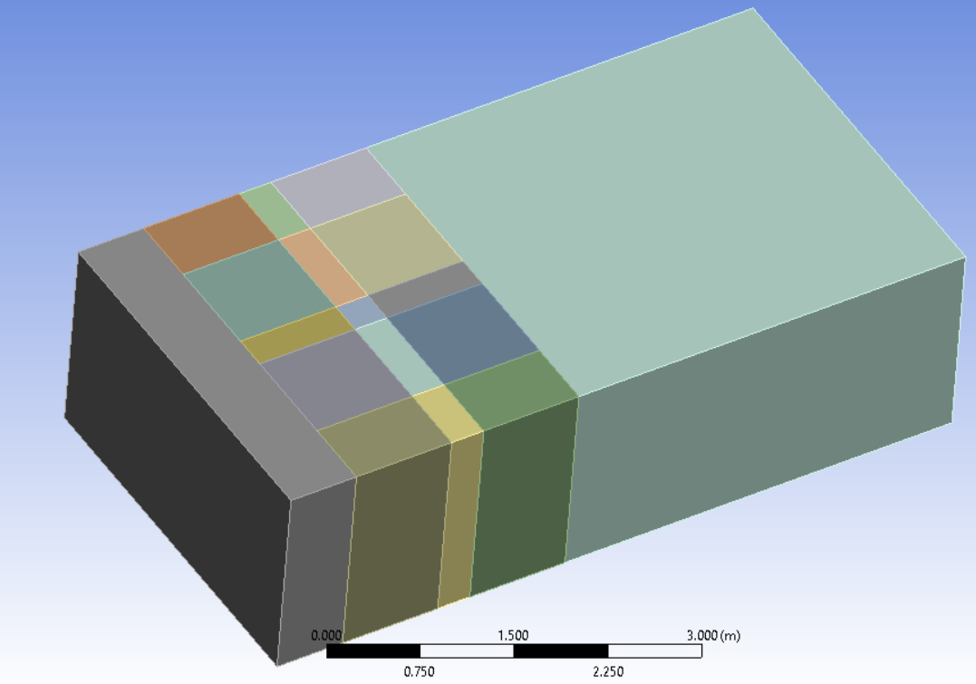
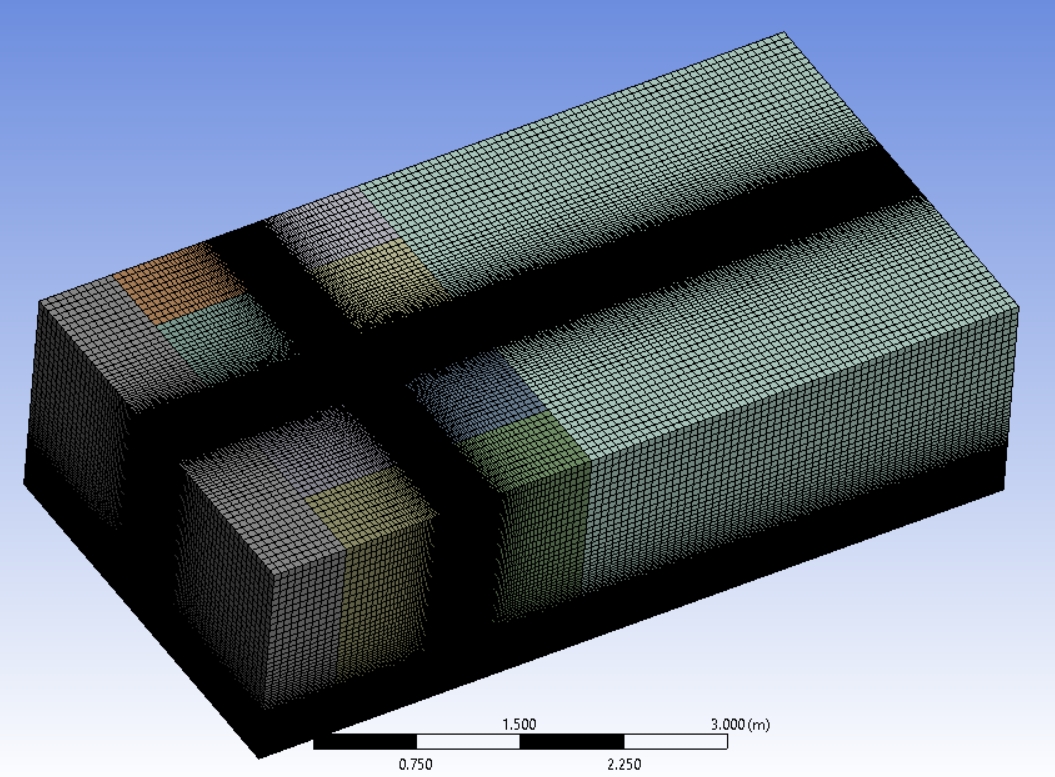
This is how I divided the domain into subdomains in Spaceclaim to be able to assign the edge side to the edges to generate the structured mesh. I also use the Multizone method to generate the hex mesh. First of all, although all the domain has been divided into parallel lines, the multizone method doesn't generate the 100% orthogonal grid, like ICEM or GAMBIT.
Then as you can see each surface has been divided into smaller surfaces; in the boundary condition it shows uniform surfaces but when I go to mesh view, the surfaces are a mess. ICEM makes everything uniform once you convert the mesh to unstructured mesh but in Ansys meshing, I don't know how to make it.


As we have an academic license, could you please let me know if there is any private training available for these matters?
December 7, 2021 at 2:22 pmRob
Forum ModeratorAs I still haven't seen the results I can't comment. Otherwise, I'd not use a structured mesh on the above as poly cells are likely to be far more economic on both meshing and solver time.
We offer training via the Learning Hub, that's bought on a per user basis and has most/all of the standard and advanced training courses available with many also recorded for your convenience. We also provide bespoke training, which based on our time: ie you pay for the trainer. Both are listed here https://www.ansys.com/training-center Note, we can only train the institute so contact needs to come from a member of staff using an official email address.
December 7, 2021 at 4:22 pmDecember 7, 2021 at 5:02 pmRob
Forum ModeratorHow do the velocity vectors and contours of velocity and pressure compare? The recirculation zone looks odd in the first image, but pathlines alone can't diagnose a problem. How was the convergence plot in each case?
December 8, 2021 at 9:15 amNimaNZ
SubscriberThe pressure distribution seems reasonable in both cases, although none of them give a proper drag coefficient (it might be because of the inlet logarithmic profile). Exactly, because we have the experimental streamlines we can judge based on that. The second one is close to the experimental results.
Convergence in the first case can go to the 1e-6 as I used SIMPLE algorithm, the second one I didn't try for more than 1e-5 (PISO algorithm makes convergence slower in my case) but it seems smooth.
December 8, 2021 at 9:48 amRob
Forum ModeratorPlease can you post the images - there's something odd going on and I want to confirm it's not a 3d effect that's making more of a difference than it should.
PISO is generally used for transient calculations, if this is steady I'd use either SIMPLE or PBCS & pseudo transient.
December 9, 2021 at 10:35 amNimaNZ
SubscriberI don't have a residual image at the moment.
Yes, it is obviously a transient solution. I am sure the problem is mesh. Just asked if it is possible to remove the blocks in Ansys meshing after the structured mesh has been generated. The ansewer is "No" I think.
December 9, 2021 at 10:37 amRob
Forum ModeratorAssuming the mesh is conformal, labelling all volumes with the same named selection will reduce the number of fluid bodies, and that then reduces the level of label splitting in the solver. If you have contact regions everywhere then it's a bit more complicated.
December 11, 2021 at 10:50 amNimaNZ
SubscriberThank you for your response. I do have contact regions, and I remember once here someone told me to delete those contact folders in Ansys meshing then generate the mesh. That was kind of helpful in terms of reducing the complexity of the mesh Transfering to FLUENT, but still, the domain has been divided into many subdomains and I think this generates an error in boundary condition interpretation during the computation process. I think that is why in advanced software like ICEM there is an option for exporting the blocking mesh to the unstructured mesh which gives a neat mesh. I wish there was the same option in Ansys meshing software, as it is more user-friendly.
December 15, 2021 at 5:36 pmRob
Forum ModeratorHaving not used ICEM CFD in many years, and not properly since the "old" version for Fluent 4 I can't comment. For 2d I tend to use Ansys meshing, and for 3d a mix of Ansys Meshing and Fluent Meshing with the workflows: more so the latter in the last couple of releases.
Viewing 15 reply threads- The topic ‘Export to unstructured mesh’ is closed to new replies.
Innovation SpaceTrending discussionsTop Contributors-
4803
-
1576
-
1386
-
1242
-
1021
Top Rated Tags© 2026 Copyright ANSYS, Inc. All rights reserved.
Ansys does not support the usage of unauthorized Ansys software. Please visit www.ansys.com to obtain an official distribution.
-

