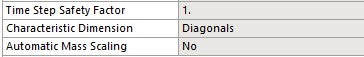
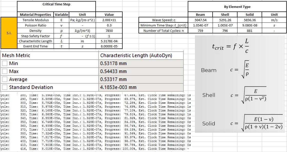
As the title mentions, I ran a simple model to test the stated process for creating a stable explicit time step as proposed by the Ansys Learning video. So in the model, all I did was create a simple 2x2x2mm Linear Hex of Structural Steel. Following the video for wave speed in a solid element, c = 5856.36 m/s . The characteristic length of this single undeformed element is described in the Explicit Analysis Guide as "The volume of the element divided by the square of the longest diagonal of the zone and scaled by (sqrt2)/3." Doing the math on that, the longest diagonal is the body diagonal of the cube, 3.464mm, and the characteristic length is then 0.3143mm. The mesh output plot, if set to "Characteristic Length (AutoDyn)" reads 0.54433mm. What is the discrepency here? If I run any model using this as my only element size (set to hard to fix its size), then program controlled gives me a time step increment in the post output. If I work back this time step by the CFL condition, the plotted characteristic length from Mesh Diagnostic does not actually give that time step. Also, the Analysis Setting of "Characteristic Dimension: Diagonal" (or any option) does not appear to change that mesh value. I understand that there may be more factors influencing the time step, such as contact, but the guidance for using CFL seems to not work either way. It seems like the best approach to getting a stable time step is to let ANSYS program control it, then take that number and reduce it as needed. I'm almost positive I have done the math right and checked units, but no matter how I try to work it, ANSYS usually gives around half of the CFL value as the initial program controlled time step.