TAGGED: -waveguide, evanescentwave
-
-
February 28, 2024 at 8:30 pm
Zhi Li
SubscriberWhat is the correct way of simulating a rectangular waveguide when the operating frequency range is right around the cutoff frequency of the TE10 mode?
The operation of my design relies on the evanescent TE10 mode. However, since the wave impedance is purely imaginary and the wave is attenuating below the cutoff, what simulation setup should be used to provide reliable simulation results? More specifically, does deembedding still work for an evanescent waveguide of arbitrary length? Should I renormalize the port impedance to a real reference impedance?
-
March 4, 2024 at 9:00 am
Jason Kalogeropoulos
Ansys EmployeeHello zIEM,
There is an Ansys Innovation Course regarding the simulation of a waveguide using HFSS, that may resolve most of your questions. Please, feel free to access it from here: Intro to Ansys HFSS Using a Waveguide Example Part 1 — Lesson 2 - ANSYS Innovation Courses
Regarding the de-embedding, yes, it works but for a defined (from the user) length.
If you want to have an impedance reference, I suggest renormalizing the port impedance to 50 ohms or any other value you desire. Keep in mind that port renormalization is a Post Processing effect. Thus, you will be able to switch this option after your simulation and compare its results without changing the initial simulation settings.
Best regards,
Jason. -
March 12, 2024 at 3:50 am
Irina G.
Ansys EmployeeHi,
I personally don't like to use modes in waveports that are below the cutoff frequency. You can test if they can be de-embedded correctly. Also note that to get S-parameters that one expect to see below the cutoff frequency without renormalizing waveports, you need to switch to Power definition of S-parameters. If possible, re-formulate the design so the lumped port is used.
-
March 15, 2024 at 9:33 pm
Zhi Li
SubscriberHi Irina,
I could not find information about the Power definition of S-parameters in the HFSS Help document. Do you know any document to which I can refer for the differences between "Generalized" and "Power"? Thank you very much.
-
-
March 15, 2024 at 9:28 pm
Zhi Li
SubscriberHi,
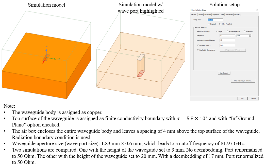
Thank you for your suggestions. Allow me to provide more details regarding my design. The simulation is intended to model an open-ended waveguide section excited by a waveport operating in the evanescent mode. The goal is to obtain information about the input impedance looking into the waveguide section of a given length terminated by free space and the radiation properties of this open-ended waveguide. The frequency of interest is below the cutoff of the waveguide's dominant mode. In addition, I want to obtain the information for different lengths. Therefore, I was hoping deembedding could be used so that I only need to simulate once for an abitrary length then for other values I can simply do deembedding to shift the reference plane. The simulation model and setup are shown below:
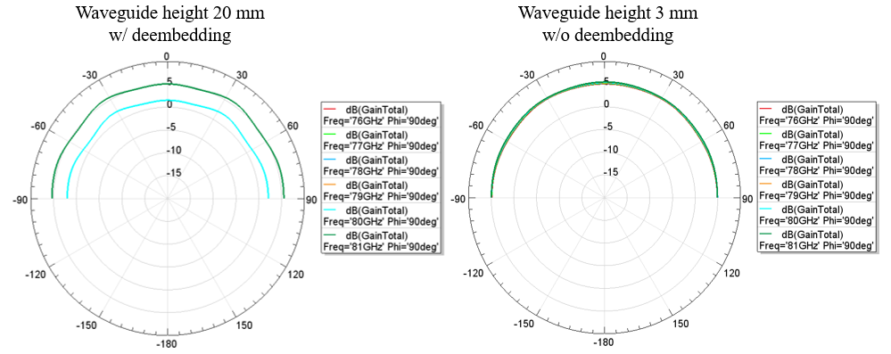
Some discrepancies are observed in the radiation patterns from the two simulations. The "Include Port Post Processing Effects" option is checked in "Excitations". In the 3-mm case, patterns at different frequencies almost overlap while in the 20-mm case, patterns only exist at 80 and 81 GHz. The discrepancies here make me wonder whether deembedding can be used in my design for the purpose mentioned above.
-
March 15, 2024 at 9:47 pm
Irina G.
Ansys EmployeeCompare rE values, not Gain
-
- The topic ‘Evanescent Mode Waveguide Simulation in HFSS’ is closed to new replies.


-
4683
-
1565
-
1386
-
1242
-
1021

© 2025 Copyright ANSYS, Inc. All rights reserved.


