-
-
November 23, 2019 at 2:22 am
mekafime
SubscriberHi
The model below does not converge for a load of 170 kN on one diagonal and -170 kN on the other, however when under load at 130 kN and -130 kN respectively the model does converge. Please what would be the mistake?
Attached File in 2019 R3
-
November 25, 2019 at 6:25 am
Aniket
Forum ModeratorAnsys Employees can not download the files. But in general, increasing substeps should help you to converge this problem.
-Aniket
Guidelines on the Student Community
-
November 25, 2019 at 9:50 am
-
November 25, 2019 at 1:31 pm
Aniket
Forum Moderatorwhat error do you get in the solve.out file?
-
November 25, 2019 at 9:01 pm
-
November 25, 2019 at 9:15 pm
peteroznewman
SubscriberElement 24213 has become highly distorted.Â
If you type a nonzero number into the Identify Element Violations field under the Solution Information folder details, then Mechanical will automatically create a Named Selection to show you that element.  If you left it zero, you can manually create a Named Selection using the Worksheet to show which element that is. Please reply with an image of that element.
One corrective action may be to improve the element shape, pre-distorting elements in that location in the meshing phase, so that as the load is applied, the deformation causes the element shape to improve as the load is applied.
Another corrective action may be to get rid of the bonded contact and replace it with bodies connected via shared topology. That might require some of the bodies to be meshed with Tet element, but those are very good at tolerating distortion.
Â
-
November 26, 2019 at 2:33 am
-
November 26, 2019 at 2:42 pm
peteroznewman
SubscriberHere is one of the elements that became highly distorted.
These are quadratic elements which don't like their midside nodes getting too far out of line. One idea is to change to linear elements while also halving the element size. This will put a node much closer to the bonded contact edge of the other part and eliminate the midside node, making elements that are more tolerant of distortion.
Getting rid of bonded contact is a better idea when it comes to modeling plasticity. With some effort, the parts could be sliced to maintain hex elements and use shared topology instead of tet elements.
-
December 10, 2019 at 7:17 pm
mekafime
SubscriberHi Peter,
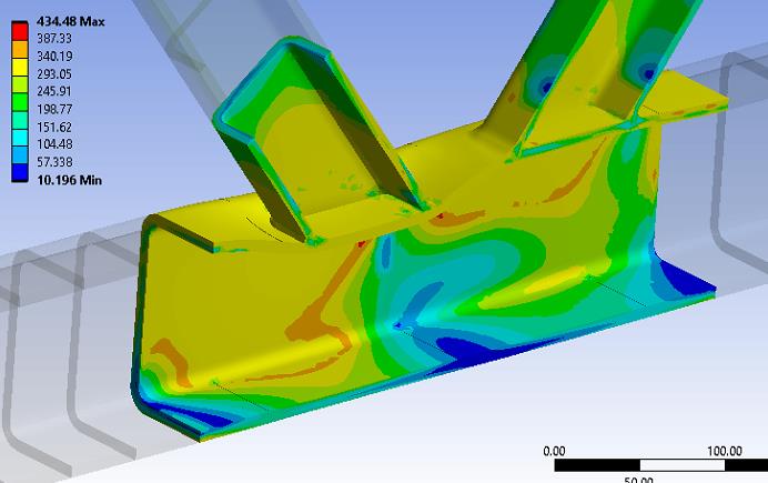
I used boolean to unite in a only, and hex elements , but when I use topology the analysis failed because I avoid use topology.
The model analyzes successfully
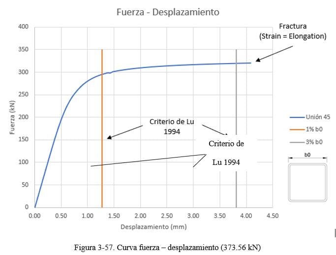
For my thesis I am analyzing this type of tubular connection by varying the separation between the diagonals and I get the Force - Displacement curve as a response, with Force being the axial force acting on the compression diagonal and the Displacement the deformation of the upper flange face (horizontal element) by action of the diagonal compression.
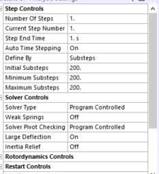
The solids to analyze them with solidworks, as I mentioned only by varying the distance between diagonals and charged to the design modeler, thus having several 3D models and several Ansys files, from which I obtain my graph and gather the curves in Excel. For the model in ansys a mesh study was made.
My problem is that:
In the first curves there is a trend, however in the following this trend is broken and there are many variations.
The end of the curve is the break point (elongation at break 23%) for the type of material used in the analysis.
What can I do to standardize, or is that the result? I also planned to make the model in design modeler and parameterize it, but if it is the same….
Please waiting for your comments.
-
December 10, 2019 at 8:47 pm
peteroznewman
SubscriberPlease reply with a more detailed description of Displacement, maybe with a sketch or image. Why is Displacement important?
Also, attach a copy of your spreadsheet in a zip file so I can look at it more closely.
-
December 10, 2019 at 10:16 pm
mekafime
SubscriberThanks Peter.
The node taken for displacement is (2 cm from the outer foot of the diagonal) :
The displacement is important because in a curve Force-Displacement , I can obtain the maximum force that I can apply to the diagonal depending on the width of the chord.
I include the model with the smallest and largest distancing.
Â
-
December 13, 2019 at 1:04 am
mekafime
SubscriberThe files are in Ansys R3
-
December 13, 2019 at 1:50 am
peteroznewman
SubscriberI ran each model you provided. Nice mesh.
What I asked for was the spreadsheet that had the Force-Displacement of all values of the parameter d.
The idea I had was to normalize Displacement by the parameter d.
Or maybe just plot data directly against the parameter d.
-
December 13, 2019 at 3:36 am
mekafime
SubscriberHi Peter,
Thanks for your time.
I add the spreadsheet of Force-Displacement.Â
-
December 14, 2019 at 10:21 pm
mekafime
SubscriberHi Peter,
I try to change the mesh, but ... nothing ! ... the result is the same all models they don´t follow a trend although some want to accomodate certain models move away from the trend.
-
December 19, 2019 at 3:35 pm
mekafime
SubscriberHi Peter
Could you normalize the displacement?
Thanks you
-
- The topic ‘Error with a higher load’ is closed to new replies.
-
3402
-
1052
-
1051
-
896
-
877
© 2025 Copyright ANSYS, Inc. All rights reserved.