-
-
October 21, 2021 at 9:13 am
i.tamunodienye2
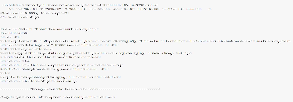
SubscriberI have tried so much to make adjustments on the time-step size, solution control etc but nothing seem to work. I started having this problem when i reduced my mesh first cell height to 1e-06. See the attached error for your understanding and please help for solution.
October 21, 2021 at 11:48 amAmine Ben Hadj Ali
Ansys EmployeeOkay that is an error message telling that the global courant number is very large. With that error message we cannot help you: you need to describe the modeling task, your setup, boundaries, mesh quality, etc..
October 21, 2021 at 12:26 pmi.tamunodienye2
SubscriberDo you mean i should describe the modeling task, setup etc in the comment box and submit here?
October 21, 2021 at 12:40 pmOctober 21, 2021 at 12:44 pmi.tamunodienye2
SubscriberGlobal Courant Number [Explicit VOF Criteria] : 0.163532
done.
This is the value of global courant (above) after making the adjustment in my previous message.
October 21, 2021 at 4:19 pmRob
Forum ModeratorCheck the mesh and speed of the flow. The error looks to be as says re the Courant Number. This generally means you're not running a small enough time step: this assumption may also explain the poor convergence. However, we need more information, ie pictures & an explanation of the model and desired information.
October 22, 2021 at 3:47 pmi.tamunodienye2
SubscriberOctober 22, 2021 at 4:00 pmi.tamunodienye2
SubscriberI have attached a word document for your attention.
The attachments are many so the comment section could not support it, hence i have sent through the attached word document.
October 22, 2021 at 4:43 pmRob
Forum ModeratorStaff aren't permitted to open or download attachments. We don't mind if you take a few posts to provide information.
October 25, 2021 at 7:51 amAmine Ben Hadj Ali
Ansys EmployeePlease share what you have put in the document in this forum: I do not download attachements.
October 25, 2021 at 1:15 pmi.tamunodienye2
SubscriberThe attachments only provided the set-up for the simulation. They are as follows:
Flow Physics
Solver: Transient and gravity (-9.81m/s2) turned on
Operating condition: 2MPa, 303 deg C, 0kg/m3
Turbulence model: k-omega SST, turbulence damping =10
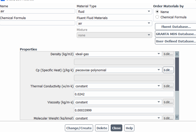
Multiphase model: Eulerian-Multi-Fluid VOF, Explicit formulation, sharp interface, interfacial diffusion turned on, 0.25 Courant, 1e-06 volume fraction cutoff, 2 phase (ideal gas and water as materials), Cp-piecewise-polynomial. Drag coefficient - anisotropic-drag, surface tension turned on, surface tension coefficient -1.406, interfacial area - ia-symmetric
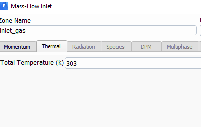
Boundary condition: For Inlet-gas: turbulent intensity-5%, hydraulic diameter-0.21m, mass flow rate-7.620921kg/s, mass-flow inlet
For Inlet-liquid: turbulent intensity-5%, hydraulic diameter-0.21m, mass flow rate: 276.6256kg/s, volume fraction-1, mass-flow inlet
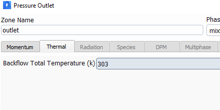
For outlet: Pressure-outlet, turbulent intensity-5%, hydraulic diameter-0.21m, backflow volume fraction-0
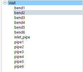
For wall: stationary wall, no-slip condition
Solution methods:

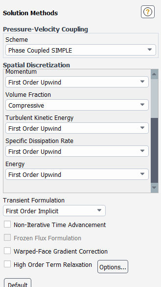
Solution control: pressure-3, density-1, body forces-1, momentum-0.7, TKE-0.8, SDR-0.8, TV-1, Energy-0.5
Residuals
 Initialization:
Firstly, the solution was initialize with the liquid in the domain. A time-step size of 1e-04 to 1e-06 was used to reduce the global courant number further down but the simulation stopped with the error below.
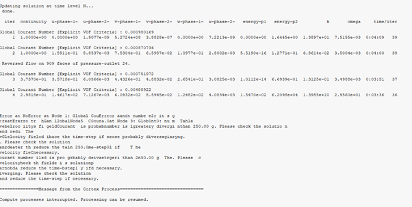 There are also messages like turbulent viscosity larger than 1.000000.
However, when i initialized the solution with the gas, the solution converged even in reverse flow condition. Anyway i am not comfortable with initializing the solution from the inlet-gas. I also changed the turbulence multi-phase model to "per phase". Also, the interfacial modelling was changed to sharp/dispersed and the volume fraction formulation to implicit. Lastly, for this case, all the spatial discretization was changed to QUICK. These changes were done when the solution was initialized with gas. However, I want to initialize from the inlet-liquid. In this case the liquid fills the domain at first while gas goes through the center
October 25, 2021 at 1:37 pmRob
Forum ModeratorDid you patch the flow to be about right or rely on hybrid initialisation? Also how does the mesh look? Just because the cell quality is OK doesn't mean you have enough cells in the right places.
October 25, 2021 at 1:56 pmi.tamunodienye2
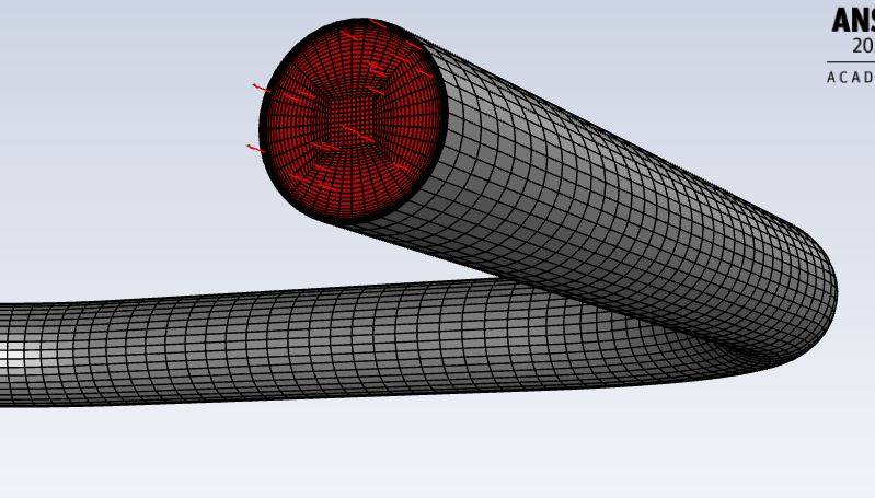
SubscriberI did not patch the flow. The flow is completely filled with liquid at initialization. The mesh was ok with just VOF and also ok when i initialized with gas(but in reverse flow). I try use other meshes and try. This is how the hybrid-initialization comes up
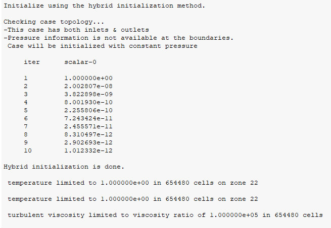 I varied the solution control several times but this did not go away.
October 25, 2021 at 1:59 pmAmine Ben Hadj Ali
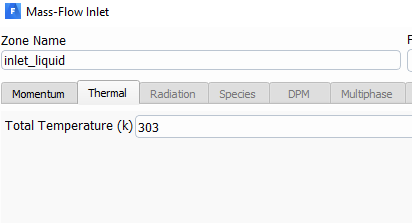
Ansys EmployeeTemperature limitations are critical here: what are you doing? Are you using expressions to do some settings?
October 25, 2021 at 2:34 pmOctober 26, 2021 at 6:40 amaitor.amatriain
SubscriberThe error messages after the hybrid initialization usually appear when one (or more) thermodynamic variables is zero at one (or more) boundaries.
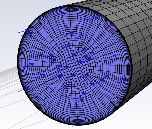
Could you please show us some screenshots of the mesh, as well as some contours of the solution after the initialization? If the contours after initialization do not make physical sense, then the simulation is useless.
October 26, 2021 at 9:06 amOctober 26, 2021 at 10:00 amRob
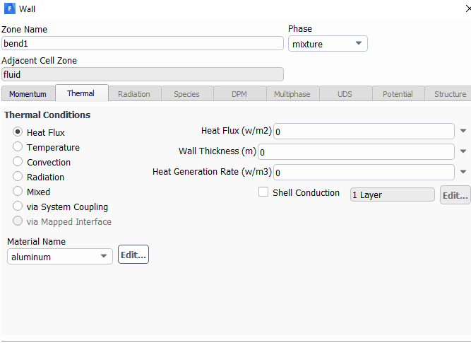
Forum ModeratorIf the walls don't allow heat transfer and there is no other heating effect how much do you expect the density to change? Re the mesh, for multiphase we also need a relatively low aspect ratio, this can be at odds with the text book y+ requirements. Either increase the streamwise resolution or reduce the near wall resolution. I'd also favour a quad pave over O-grid to avoid jumps in cell size.
October 26, 2021 at 10:29 amaitor.amatriain
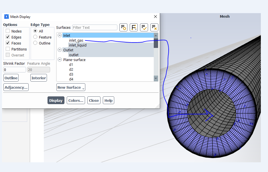
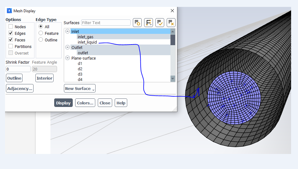
SubscriberWe need more information. Where are gas and liquid inlets? Could you please show us contours of pressure and velocity after the initialization?
October 26, 2021 at 11:13 amOctober 26, 2021 at 1:03 pmRob
Forum ModeratorWhat are the flow conditions on the two inlets? Have you patched a region in downstream of the inlet so each boundary is flowing into material of it's own phase?
October 26, 2021 at 1:22 pmi.tamunodienye2
SubscriberGas mass flow rate = 7.620921 kg/s
Liquid mass flow rate = 276.6256 kg/s
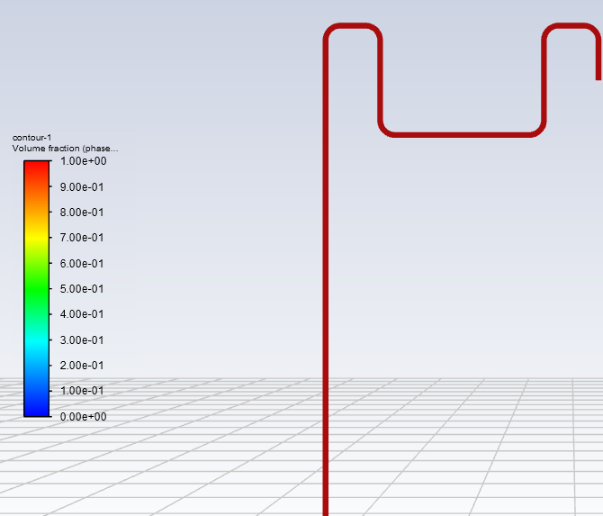
I did not patch anywhere. The whole volume (fluid domain) was initialized with liquid in the first place before running the simulation. So the point is while the liquid fill the fluid domain, the gas will flow through the middle. See a void fraction result of VOF below.
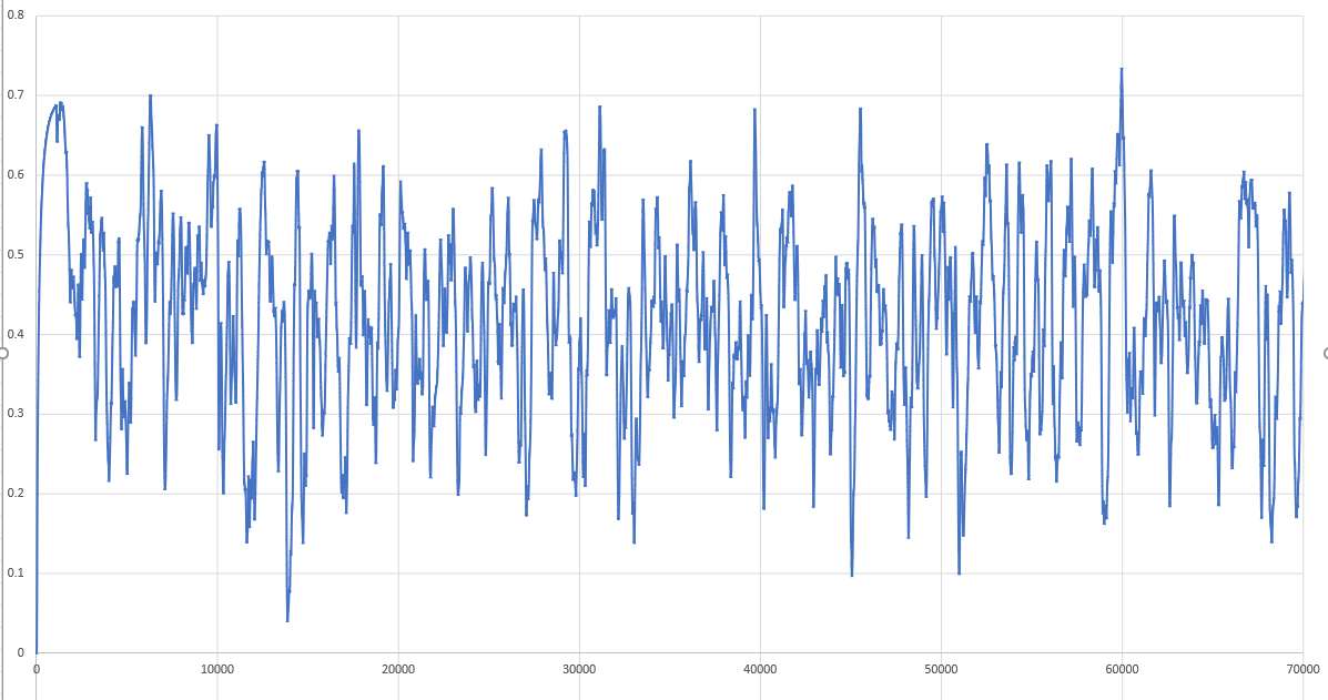 The fluctuation is the passage of the gas and liquid phases. The gas initially flow from 0 to 0.7 then followed by liquid and so on. This result was obtained with VOF and not multi-Fluid VOF
October 26, 2021 at 1:37 pmRob
Forum ModeratorIf you put your data into a Baker Chart what flow regime are you in?
October 26, 2021 at 2:09 pmi.tamunodienye2
SubscriberThe flow conditions are as follows:
Gas mass flow rate: 7.620921 kg/s
Liquid mass flow rate: 276.6256 kg/s
Note, i did not patch the fluid domain because it was completely filled with liquid (initialized with liquid phase) as show below hence i felt no need for patching.
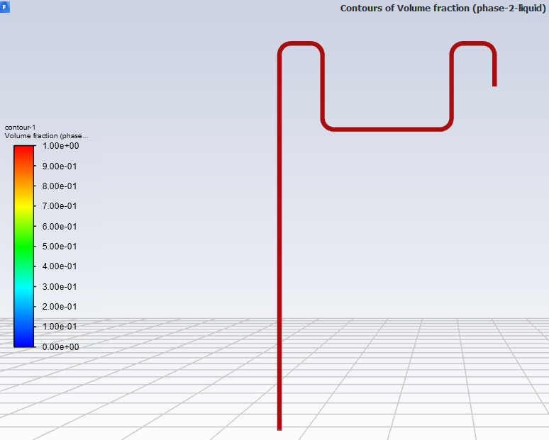
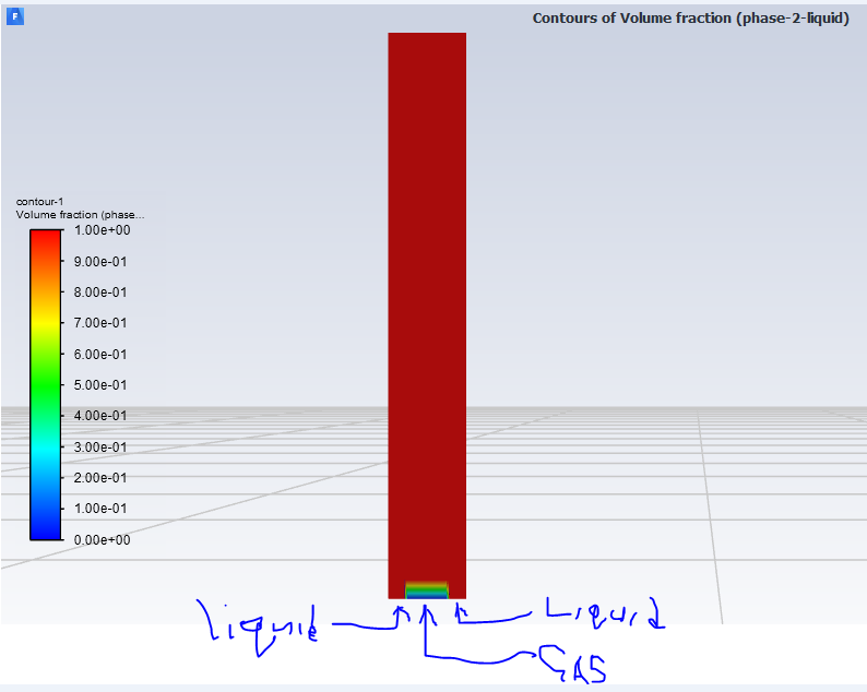
It will interest you to know that same mesh gave me a converged solution in VOF simulation as shown below.

October 26, 2021 at 2:56 pmi.tamunodienye2
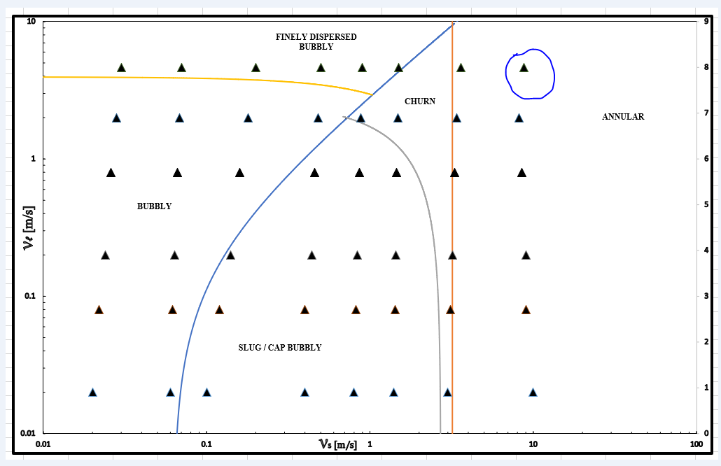
SubscriberI constructed my flow map regime based on Taitel and Duckler transition equations for vertical upward flow. The pressure is 2MPa and density of 25kg/m3 for an ideal gas and water, t = 30 deg C, pipe dia = 0.21m. Flow maps with these properties don't exit. See below. The circled triangular in the annular flow regime is what i am using to run the simulation. I believe i didn't obtain full annular because the entrance length wasn't long enough. Though it was annular during the first 10,000 iteration before mixing
October 26, 2021 at 2:57 pmaitor.amatriain
SubscriberAs says, you should create a finer mesh
October 26, 2021 at 2:58 pmi.tamunodienye2
SubscriberPlease note the superficial velocities were converted to mass flow rates before using in ansys fluent
October 26, 2021 at 3:12 pmOctober 26, 2021 at 3:59 pmRob
Forum ModeratorIf you use Workbench Meshing or Fluent Meshing it's a few button clicks to remesh. Aim for an aspect ratio near around 1 next to the inlet and for the first few diameters plus at the bends. Patch in the near inlet cell to be the correct phase for the adjacent inlet too.
October 26, 2021 at 3:59 pmRob
Forum ModeratorTo add, what is the inlet velocity for each phase?
October 26, 2021 at 4:28 pmi.tamunodienye2
SubscriberThe superficial velocities are as follows
Gas superficial velocity = 8.8m/s equivalent of 7.620921 kg/s (mass flow rate)
Liquid superficial velocity = 8m/s equivalent of 276.6256 kg/s (mass flow rate)
I used ICEM CFD in this meshing. Never used Fluent meshing before. I did not try workbench meshing with this geometry.
...and for the first few diameters plus at the bends. Patch in the near inlet cell to be the correct phase for the adjacent inlet too.
I am not clear with the above statement. Is there diagram to explain this?
October 27, 2021 at 5:48 amAmine Ben Hadj Ali
Ansys EmployeeSo you expect having an annular flow? And you use a core patch? I am not sure if VOF model is the right choice here given the short entrance length where the flow mixes again. This kind of flows are really sensible to initialization and numerics. You need to converge deep every time step.
October 29, 2021 at 4:01 ami.tamunodienye2
SubscriberThe slug flow regime is more important in my work. The reason i use VOF
Viewing 32 reply threads- The topic ‘Error report in multiphase flow simulation’ is closed to new replies.
Innovation SpaceTrending discussionsTop Contributors-
5054
-
1764
-
1387
-
1248
-
1021
Top Rated Tags© 2026 Copyright ANSYS, Inc. All rights reserved.
Ansys does not support the usage of unauthorized Ansys software. Please visit www.ansys.com to obtain an official distribution.
-
The Ansys Learning Forum is a public forum. You are prohibited from providing (i) information that is confidential to You, your employer, or any third party, (ii) Personal Data or individually identifiable health information, (iii) any information that is U.S. Government Classified, Controlled Unclassified Information, International Traffic in Arms Regulators (ITAR) or Export Administration Regulators (EAR) controlled or otherwise have been determined by the United States Government or by a foreign government to require protection against unauthorized disclosure for reasons of national security, or (iv) topics or information restricted by the People's Republic of China data protection and privacy laws.

