TAGGED: -Ansys-Maxwell-electronics, ansys-circuit
-
-
January 10, 2024 at 3:44 pm
Zhengting.Wu
Subscriberhello there,
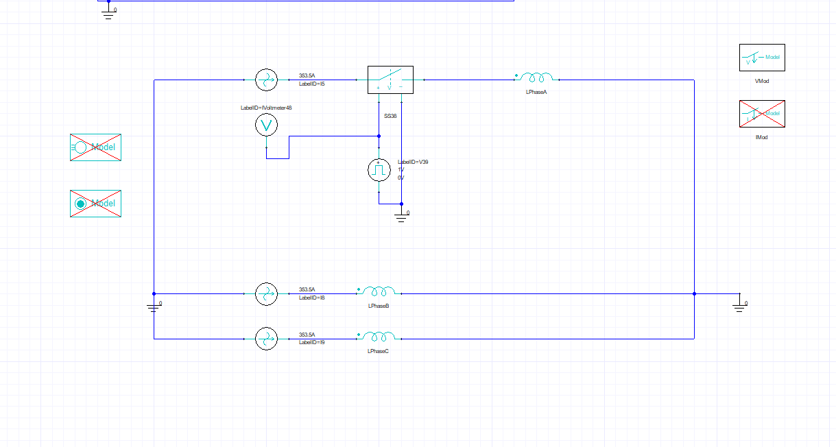
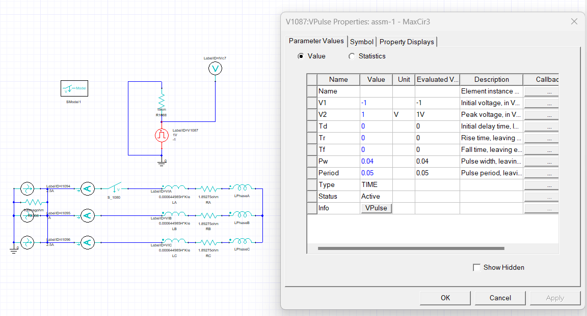
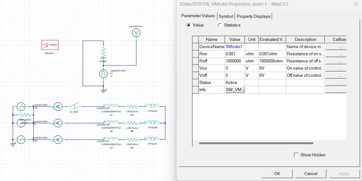
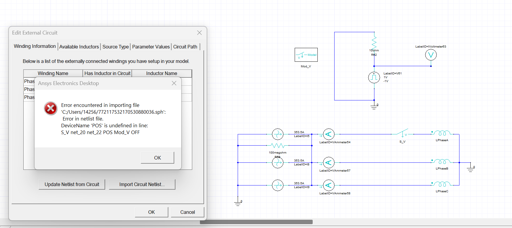
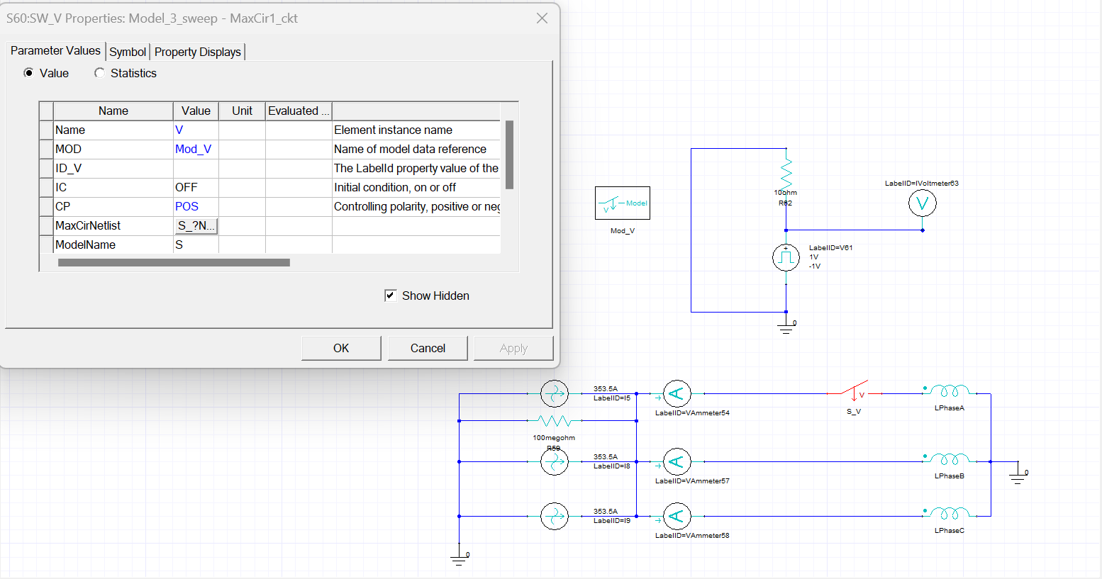
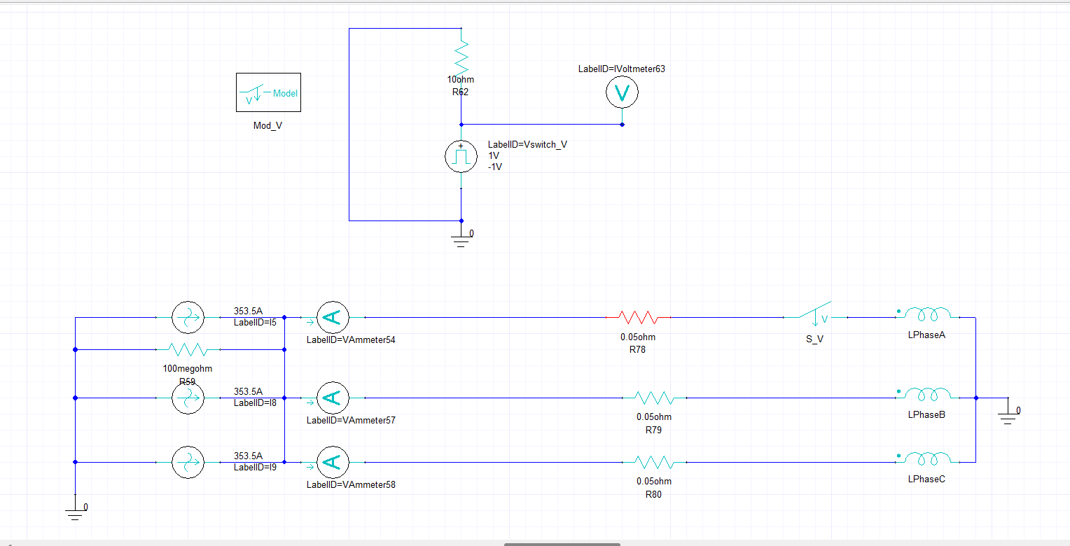
I want to do a failure test for my 3-Phase PMSM Model. I want to see how will the Motor acting when suddenly one Phase has open circuit fault. So I add a Voltage Controlled Switch, with a Pulse Voltage Source as the Controlling Source, to control the A phase and course a open circuit(see in the following pics).
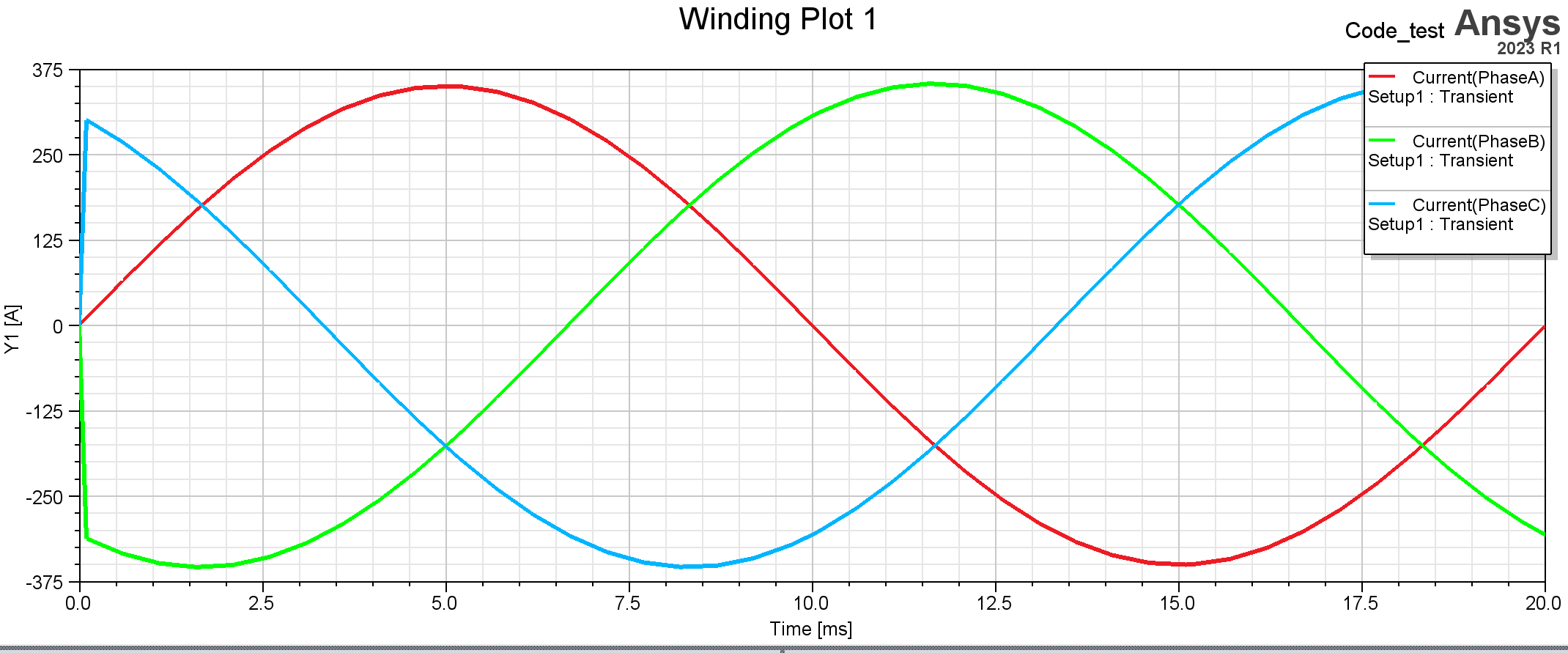
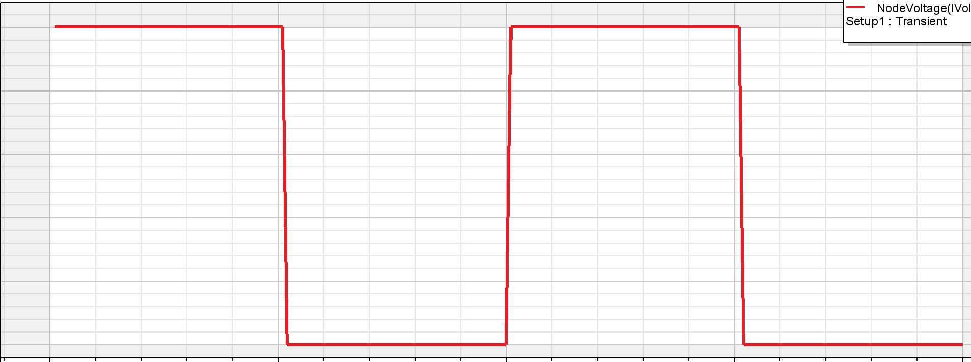
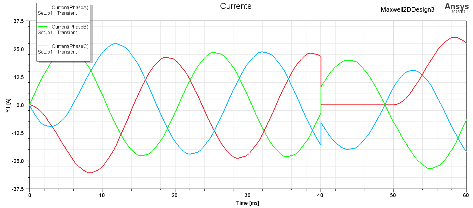
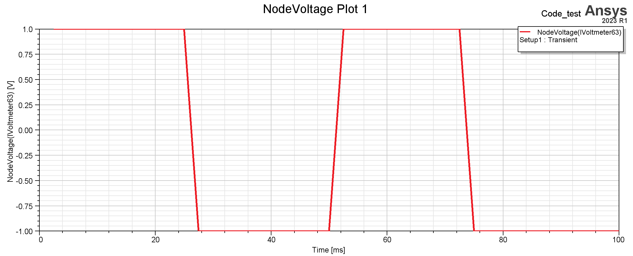
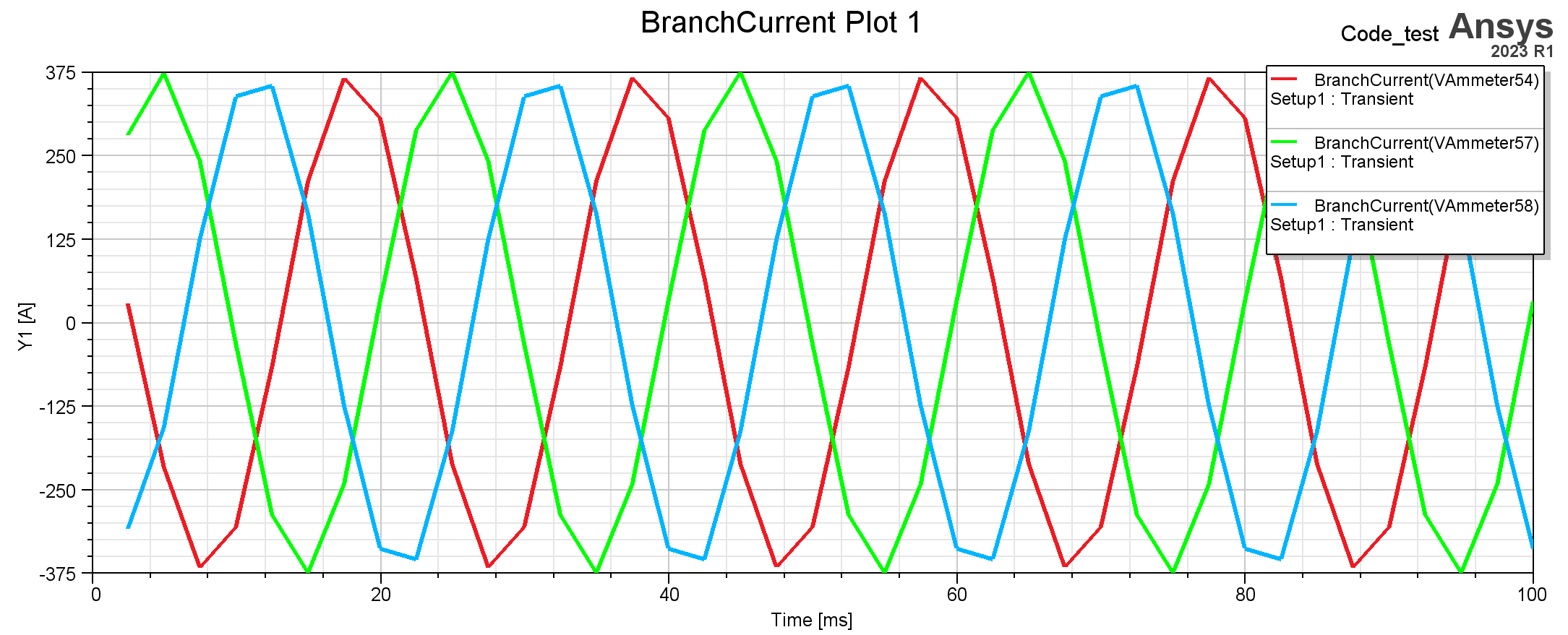
But the Switch did not work. As you can see: the Pulse Voltage worked will, but the current of Phase A did not change along with it. I tried many times and found out that it was the Switch who wasing working.
Please help. The screenshots of circuit, settings and results are attached. THANKS!
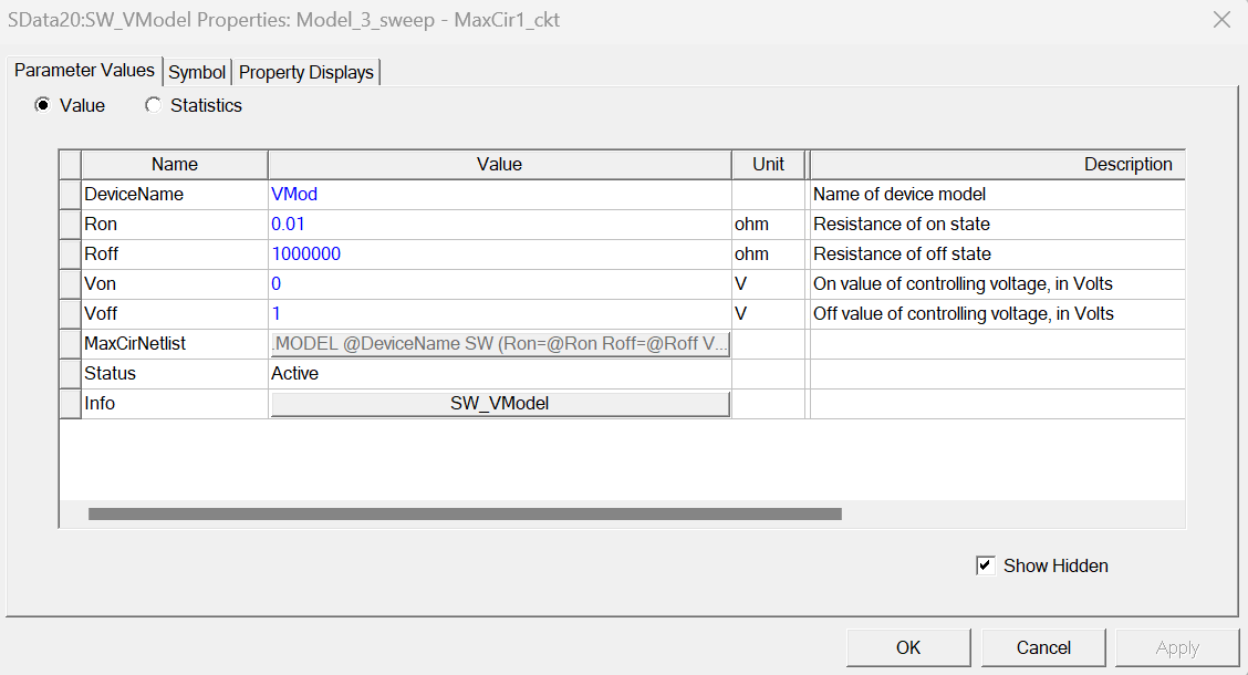
Mod setting
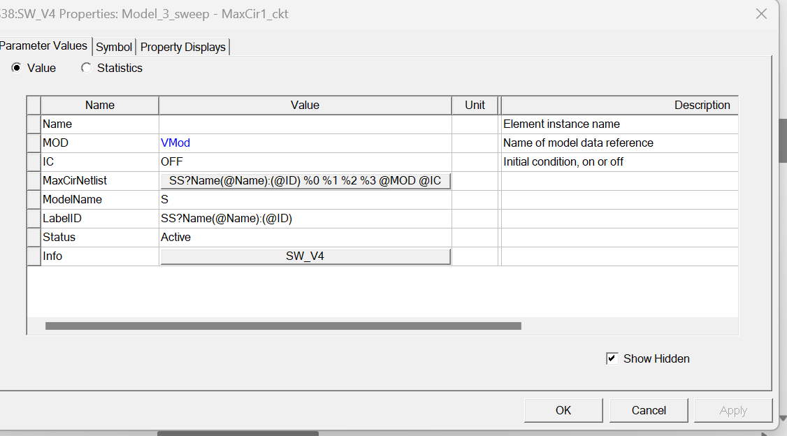
Switch setting
circuit
-
January 12, 2024 at 6:18 am
Reshmi Raghavan
Ansys Employee-
January 15, 2024 at 9:00 am
-
-
January 15, 2024 at 11:02 am
Reshmi Raghavan
Ansys EmployeeHello Zhengting,
Please check the switch model, if the name POS is used in the properties or not ?
-
January 15, 2024 at 11:18 am
-
-
January 15, 2024 at 11:32 am
Reshmi Raghavan
Ansys EmployeeHello Zhengting,
The reference to the voltmeter has not been provided in the switch property, ID_V is empty. Please enter the name of the voltmeter used for measuring the voltage from the pulse circuit.
-
January 15, 2024 at 11:54 am
Zhengting.Wu
Subscriber
-
-
January 15, 2024 at 12:35 pm
-
January 16, 2024 at 3:40 am
Reshmi Raghavan
Ansys EmployeeHello Zhengting,
Please share the error messages, its not visible.
-
January 16, 2024 at 10:00 am
Zhengting.Wu
SubscriberHello!
Here are the error mssages when I didnt add resistors in the circuits :
[error] Time step at 0 sec completed, process solver2d error: Internal Solver Error: 'Unable to create extnlckt_1.par file. '. Please contact Ansys technical support. (10:56:06 AM Jan 16, 2024)
[error] Error in estimating the memory for Auto HPC. (10:56:06 AM Jan 16, 2024)
[error] Simulation completed with execution error on server: Local Machine. (10:56:06 AM Jan 16, 2024)After I added one resistor for each Phase, there were no error messages anymore, but the switch didnt work. I added the switch in Phase A but the current of Phase A remained unchanged.
-
-
- The topic ‘Error in Maxwell circuit Com.: Voltage Controlled Switch with Controlling Port’ is closed to new replies.


-
4934
-
1638
-
1386
-
1242
-
1021

© 2026 Copyright ANSYS, Inc. All rights reserved.

