-
-
July 22, 2022 at 8:43 pm
agarwa20
SubscriberHello,
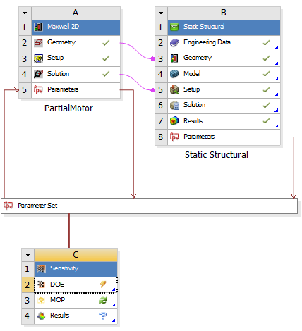
I am running a coupled EM and stress simulation. I have fillets in my geometry but the EM analysis runs well. For any design point variation, using optiSlang DOE I am getting an error in the static structural analysis as below due to which all my design points fail:
When I delete the fillets from the geometry I don't get this error. Also by manually entering the design parameters of the variation in mechanical, no error is obtained and the simulation runs. Kindly help me resolve this issue.
-
July 26, 2022 at 6:47 pm
Gary_S
Ansys EmployeeHi
Maybe try a mesh size control (edge sizing or face sizing) on the fillets.Gary
-
July 27, 2022 at 1:41 am
agarwa20
SubscriberHi. I did that but the error persists. Do you have any other suggestion?
-
-
July 27, 2022 at 1:01 pm
Gary_S
Ansys EmployeeIn the error message, it shows Fillet1=0, Fillet2=0, Fillet3=0, Fillet4=0. Is this correct?
Beyond that, you can set Parameters to Retain the Failed Design Point, then we can open that DP independently and see why the failure.
https://ansyshelp.ansys.com/account/secured?returnurl=/Views/Secured/corp/v222/en/wb2_beta/retain_failed_design_points.html?q=failed%20design%20pointsBy default, Workbench does not retain design points after they are solved or if they fail.
To keep the calculated data and/or files for design points that fail:
In the Project Schematic, double-click the Parameter Set bar.
To save the failed design point files, in the Properties view, select the Keep Failed Design Points Files (Beta) check box.
To save the failed design point calculated data, in the Properties view, select the Retain Failed Design Points (Beta) check box.
-
July 27, 2022 at 5:16 pm
agarwa20
SubscriberHello. Thank you for your reply. The design point showing Fillet1=0, Fillet2=0, Fillet3=0, Fillet4=0 is correct. When I use the optiSlang DoE I can see the failed design points, even though the results are unavailable. Even in the parameter set I can see the input design parameters combination without the response.
Also there were some other failed design points which I checked manually and they worked in mechanical separately. But when I connect the EM to the stress the same combinations give error.
-
July 27, 2022 at 5:59 pm
Gary_S
Ansys EmployeeWere you able to use the "Retain Failed Design Points" and open a failed project?
-
July 27, 2022 at 8:17 pm
agarwa20
SubscriberHello. No, I couldn't find that option
-
July 27, 2022 at 8:21 pm
Gary_S
Ansys EmployeeEnable Beta FeaturesIn Ansys Workbench, Tools > Options > Appearance…scroll down to “Beta Options” and check the box
Then, follow the above instructions for Retaining Design Points.-
July 28, 2022 at 6:33 pm
agarwa20
SubscriberThank you I am now able to select the retain design points. But I was able to view the failed design parameter combination earlier as well. How should I utilise this retained design point?
-
-
July 28, 2022 at 6:56 pm
Gary_S
Ansys EmployeeHi !
When Workbench updates design points, it normally deletes each individual database, result files etc.
This is done intentionally to save disk space.
When you enable the "Save Failed Design Point", it should create a new Project for each failed DP.So, Update all design points.
Look in your Project Folder, and see if there is {ProjectName_dp{number}, like MyProject_dp2.We should then be able to open such project, try to update from inside Mechanical, and hopefully see additional errors or clues.
-
July 29, 2022 at 2:03 pm
agarwa20
SubscriberHello. I am unable to open the failed design points separately. I can see them saved with the extension .wbdp
-
July 29, 2022 at 9:48 pm
agarwa20
SubscriberFor the failed design point, in the mech folder, the .rst result file or the .dat input file is not generated at all. So I cannot open it in mechanical separately. Do you have any input on this?
-
July 29, 2022 at 10:26 pm
Gary_S
Ansys EmployeeFor Open In Mechanical, Open in "Workbench Mechanical" (Static Structural). See if you can, and try to solve. See if it shows more errors.
-
July 30, 2022 at 1:59 am
agarwa20
SubscriberHello. I am trying that, but the .rst file which should be generated for each design point is not being generated for these failed design points.
-
-
August 1, 2022 at 12:32 pm
Gary_S
Ansys EmployeeAnsys Workbench Mechanical uses a .mechdb file extension. Are there any .mechdb files present?
-
August 1, 2022 at 9:40 pm
agarwa20
SubscriberHello. The .mechdb or .rst files are not being generated. I retained a failed design point (dp2) which displayed the same error- Unable to update setup. Unable to write APDL input file.
In the results I can see that I have a folder for design point 2 and inside I have the following subfolders:
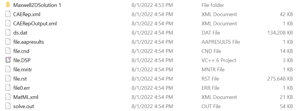
The DM folder is empty. Inside the MECH folder I can see the Maxwell solution folder and the following files without any .mechdb file:
While running the simulation, first the Maxwell solution gets updated, then the structural analysis update starts, but as soon is starts it throws the error message and moves to the next design point.
Also, for the first initial design point the analysis was successful as I am able to run any valid parameter variation manually in mechanical and the following files were available from it for the design point 0:
-
August 2, 2022 at 12:57 pm
Gary_S
Ansys EmployeeSo it seems like when the update begins, Mechancial immidiately crashes, thus no .mechdb created, and no APDL input file.
- Possibly the Static Structual is corrupt. Try deleting it and recreating it.
- Or possibly the settings became corrupt.
Exit Ansys completely.
In the File Explorer address field
Enter: %APPDATA%
...An Explorer Window will open
Open the Ansys folder...
Rename the v221 folder to v221.old for the appropriate version.
( v221 = 2022R1, v212 = 2021R2, etc) -
August 2, 2022 at 3:56 pm
agarwa20
SubscriberThank you. I deleted and recreated the structural block but the error persists. Now I also tried renaming the folder v221 to v221.old but the same error is occurring. However, after renaming this folder, when I dont transfer the EM forces to structural, the simulation is running fine. Maxwell and mechanical are updating separately with just same geometry being transferred but I still don't have the .mechdb file. There is a .dat file and .rst file . Do you have any input on this?
-
August 2, 2022 at 6:13 pm
Gary_S
Ansys EmployeeCan you plot EM force, and run the simulation with AEDT window open to check if there is a valid EM forces result?
-
August 2, 2022 at 7:32 pm
agarwa20
SubscriberThe EM analysis is running without error and torque is being generated. I will still check for the forces
-
-
August 2, 2022 at 7:49 pm
agarwa20
SubscriberFor the designs which are running without the transfer of EM forces to mechanical, some of the designs run completely, but the others throw the following error message after which immediately next design point starts to update:
In this simulation without transferring EM forces, the structural component is updated first and then the Maxwell solution is updated.
-
August 2, 2022 at 7:58 pm
Gary_S
Ansys EmployeeModel is synonymous with Mesh, so something in the mesh branch is not correct....maybe a mesh controls is not scoped properly, or is losing scope during that particular DP update. We should be able to "retain" Design Points, and open the _dp4 project and see what the issue is.
-
August 5, 2022 at 1:17 pm
Gary_S
Ansys EmployeeOne of my OptiSlang colleagues has some advice on your issue:
1. Update in Foreground, dont use RSM (Remote Solve Manager) as it is not necessary.
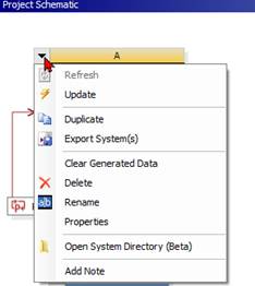
2. For optiSLang studies a best practice would be to remove all unnecessary files from the workbench project. For both components they can do a “Clear Generated Data” you can click on the drop down of the component and select it from there.
This should force workbench to always update the corresponding files and not use outdated ones.
3. Run optiSLang not within workbench (as here) but instead call workbench from optiSLang. For that you need to work in optiSLang and but then you can get a very robust setup, e.g. running always one Design in a study starting from a reference project. But due to AEDT in Workbench file paths get easily very long and workbench can only handle 256 characters, so be aware of that.
-
August 5, 2022 at 1:26 pm
agarwa20
SubscriberHello. Thank you. I used the update in Foreground option for these simulations. To check if using OptiSlang was creating the issue, I also tried with the response surface based DoE in Workbench and got the same errors.
-
August 5, 2022 at 1:44 pm
Gary_S
Ansys EmployeeOne thought I had was the 2D/3D analysis type setting.
For a 2D analysis to be valid in Mechanical, the geometry must be flat in the XY plane with Z=0.
Maybe the Fillet is causing issue with this? -
August 5, 2022 at 2:21 pm
agarwa20
SubscriberI checked the different views and Z seems to be 0 in the case with fillets. I checked by replacing the fillets with center point arcs, and faced the same problem. Earlier, the problem I was facing was that the simulation was running only when there were arcs in the geometry instead of fillets. When I deleted the fillets my simulation would run without transferring EM forces.
Now, after trying out the changes you suggested, and I think after renaming the Ansys folder, the geometry even with the fillet works when EM forces are not transferred (like the geometry with center point arcs). Also in this case even though the folders for the failed design points did not contain .mechdb file, I manually checked the parametric combinations which failed and they were leading to some geometry intersection (so they should fail). When EM forces are transferred I get the same error messages and the simulation does not proceed for that design point even though there is no geometry intersection for certain combinations.
-
August 5, 2022 at 2:40 pm
Gary_S
Ansys EmployeeIt may be that Mechanical is crashing and we cant see it happen.
Look in your %TEMP% folder for AnsysWBDumpFile.dmp.
Make not of the date time of this file.
Run your DPs.
See if the date time of the .dmp is changing. -
August 17, 2022 at 12:08 am
agarwa20
SubscriberHello,
Currently I am carrying out the simulations without transferring EM forces to mechanical. In the stress analysis setup, I am checking the maximum stress (Von Mises) at only selected edges of the air pocket instead of the entire rotor body. When I manually run some combinations with change in two radiuses of the air pocket I obtain a maximum stress of around 585MPa.
When I run the combinations with the design of experiments based on response surface block in the Workbench /optiSlang DoE, I obtain much reduced stress maximum stress values (185MPa). On verifying manually the same design combination in mechanical I obtain the correct stress of around 550-600Mpa. Is there some other way to take the stress for a particular area or is there some mistake in this method?
-
July 14, 2023 at 4:16 pm
Sean
SubscriberMine does the same thing when I suppress 4 of my 10 gaskets in the Mechanical modal window. "Update failed for the Setup component in 1-2-4-6-8-10. Unable to update setup. Unable to write APDL input file." My only way to resolve my issue so far is to unsuppress certain gaskets or to suppress them in spaceclaim. No RST is generated in mine either.
-
July 17, 2023 at 3:04 pm
Gary_S
Ansys EmployeeIf a DesignPoint fails for any reason, a good first step to troubleshoooting is to Export the given design point to a new Project, then open such project and see what is wrong.
Exporting Design Points to New Projects
To work with the calculated data for a design point other than the current design point, you can export the design point to a separate project. A new project is created for each design point that is exported.
When you export a design point, if the design point has already been exported, the existing exported files are overwritten.
Note: DesignXplorer data is not a part of design points and is not exported. DesignXplorer is a consumer of design points but does not define design points. Consequently, it is not involved when a design point is updated, or by extension, exported.
To export design points:
To open the Table pane, double-click the Parameters cell of a system or the Parameter Set bar.
In the Table pane, select the design points.
Right-click the selection and select Export Selected Design Points from the context menu.
The data of each design point is saved to a new project, named
filename_dpn(where dpnindicates the number of the exported design point), with a project file namedfilename_dpn.wbpj. Working files are saved to afilename_dpn_files directory that is a sibling to the originalfilename_files project folder.
-
- The topic ‘Error in mechanical (fillet)- Unable to write APDL input file’ is closed to new replies.


-
5069
-
1770
-
1387
-
1248
-
1021

© 2026 Copyright ANSYS, Inc. All rights reserved.


