TAGGED: constraint, design-optimization, direct-optimization
-
-
September 10, 2023 at 8:27 am
Md_Salem
SubscriberHello everyone,
I am doing an optimization on ANSYS Workbench using direct optimization.
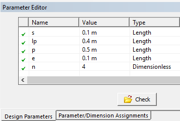
I suppose to optimize a design moudular configuration of a square patern of (n) patches attached to a plate of (l) length, where
(s) is the distance between the start of the plate and the first patch.
(lp) is the patch length.
(p) is the pitch between patches.
(e) is the distance between the last patch and the end of the plate.
I need to set an equality constraint or equality relationship between the shown parameters, such that
l = s+ lp + n*p + e
given that (l) is a constant while (s,lp,n,p,e) are optimization parameters
Could anyone help me with that problem?
Regarads
-
September 10, 2023 at 11:33 am
peteroznewman
SubscriberDon’t you have another constraint? lp < p
Use DesignModeler and create input parameters: s, lp, n, p and e.
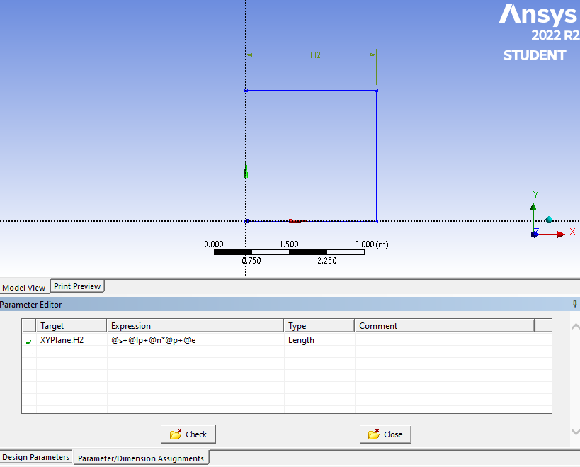
Sketch a rectangle. Apply a constraint of equal lengths to force it to be a square. Add a horizontal dimension to size the square. After dimensioning, go to the Parameter/Dimension Assignments tab of the Parameter Editor and type in the expression that constrains the length to be equal to your equation.
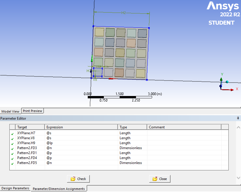
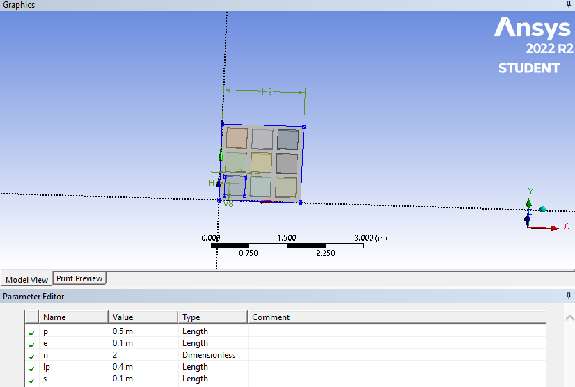
Turn that sketch into a surface or solid. Create another sketch, use the equal constraint on two edges, and dimension the length of the patch and the offsets for the s parameter. Extrude that into a solid using Add Frozen so it is a separate Body. Use the Pattern menu to copy that solid according to the n and p parameters. Note that in DesignModeler, the n stands for the number of copies of the original, so when n = 4, you get a total of 5 x 5 patches.
Now you have a completely parametric model that obeys the constraint equations, but you have to be aware to keep lp < p.
-
September 11, 2023 at 6:45 am
Md_Salem
Subscriber@peteroznewman
I appreciate it so much, I will try it.
lp
Regards
-
December 11, 2023 at 4:19 pm
Md_Salem
SubscriberHello peteroznewman
I get your point, however I'm wondering whether there's any way to ensure the symmetry of my design. Specifically, how can we assure that parameter (s) is always identical to parameter (e)?
Regards
-
-
December 11, 2023 at 10:45 pm
peteroznewman
SubscriberSimple, just go to each place where you used parameter s and replace it with an e, then you can delete parameter s. That will guarantee symmetry.
-
December 12, 2023 at 8:33 am
Md_Salem
SubscriberI got it , do you mean to make the Target (XYPlane.H2) Expression (2*@s+@l+@n*@p) instead of (@s+@l+@n*@p+@e) ?
regards
-
-
December 12, 2023 at 11:48 am
peteroznewman
SubscriberYes, that is correct.
-
January 2, 2024 at 9:31 pm
Md_Salem
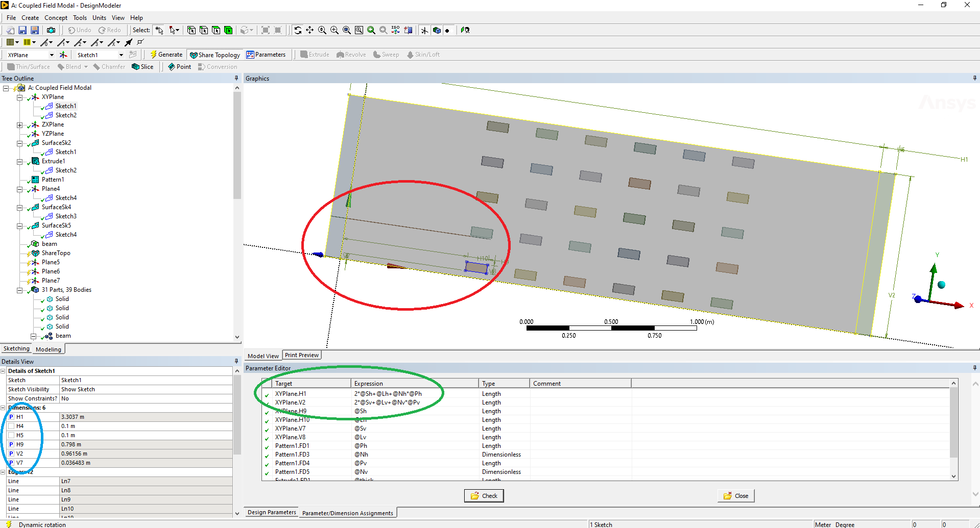
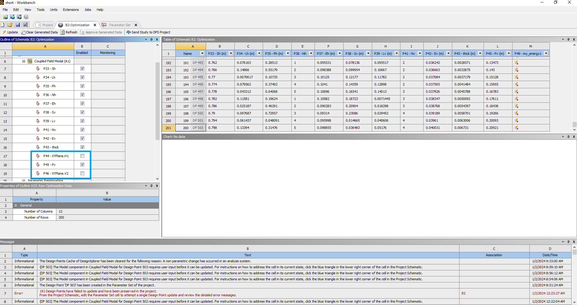
SubscriberHello peteroznewmanI tried the methodology you addressed and set up my optimization problem.Unfortunately, some design points generated by the optimizers made the overall problem size bigger than the plate size, as shown in picture 1 (the red ellipse represents the original size of the plate), where the optimizer assumed sizes for the patches and pitches between them larger than the original plate size, and hence, the dimension H1, which is the target, was changed consequently as it was the target of the first expression. .... in some other cases, the opposite thing happened (when the sizes were smaller than the original size, it changed the dimension H1 to smaller), despite the fact that I didn't add it to the optimization parameters as shown in picture 2. How do I keep the sizes H1 and V1 fixed throughout the optimization problem and keep the changes in the other dimensions that eventually lead to the same H1 and V1?Regards
-
-
January 3, 2024 at 3:51 am
peteroznewman
Subscriber”How do I keep the sizes H1 and V1 fixed throughout the optimization problem and keep the changes in the other dimensions that eventually lead to the same H1 and V1?”
First of all, it’s V2 not V1, am I right?
I don’t understand what you mean by keeping H1 and V2 fixed. You have equations that calcuate H1 and V2 from input parameters such as @Nh and @Ph that take on different values. The equations for H1 and V2 make sure the plate is large enough to contain all the patches with a margin. H1 and V2 can’t be kept fixed, that makes no sense.
-
January 3, 2024 at 9:31 am
Md_Salem
SubscriberHello peteroznewmanو
It is really V2 not V1 Excuse me for this mistake.
I think there is a misunderstanding here. My problem was to parameterize the configuration of the soild blocks array (such as @Sh,Lh,Nh,......) in such a way that it would be kept inside the plate fixed dimensions H1 and V2 as a constraint. What happened here in this optimization problem was a change in the dimensions H1 and V2 according to the array parameters.
I hope I can clarify the point.
Regards
-
-
January 3, 2024 at 12:35 pm
peteroznewman
SubscriberAh, I see what you mean. Referring to your original post, the length (l) of a square plate is fixed. Yes, I missed that when I wrote some equations for the sketches, but you missed that my equations created a variable sized plate until now, though if you look back at the images I posted, the size of the plate is clearly changing as measured by the ruler in the images.
The dependent parameter is no longer the length (l or H1 and V2) of the square plate, which is now to be a fixed constant. You need to write different equations and add some new constraints to make that happen. You will need to impose constraints because otherwise, the patch array will exceed the fixed size of the square plate.
In my previous replies, I mentioned that you must keep lp < p. How did you do that?
-
January 3, 2024 at 12:55 pm
Md_Salem
SubscriberHello peteroznewman
I tried to add this relationship (between H1 and the array parameters) as a constraint to the optimization problem. The main problem I have faced with this procedure is that the only operators in the constraints provided by the optimizer were (<=) or (>=) .
This operator led to an uneven distribution of the array over the plate length (H1)
So, I asked for help with this issue
Regards
-
-
January 3, 2024 at 1:10 pm
peteroznewman
SubscriberPlease show with a screen image how the constraint lp <= p was applied in the optimizer.
In my model, I used equality constraints in the sketches to keep the plate and patches square and imposed a square array.
In your model, you have not done that. You created two parameters for each variable (subsript v and h) so the patches are not square and the array dimensions are not equal. Is it your intention to allow rectangular patches and rectangular arrays on a square plate?
-
January 3, 2024 at 5:35 pm
Md_Salem
SubscriberYes, my design is a rectangular plate of 0.8 m in the x direction and 0.24m in the y direction.
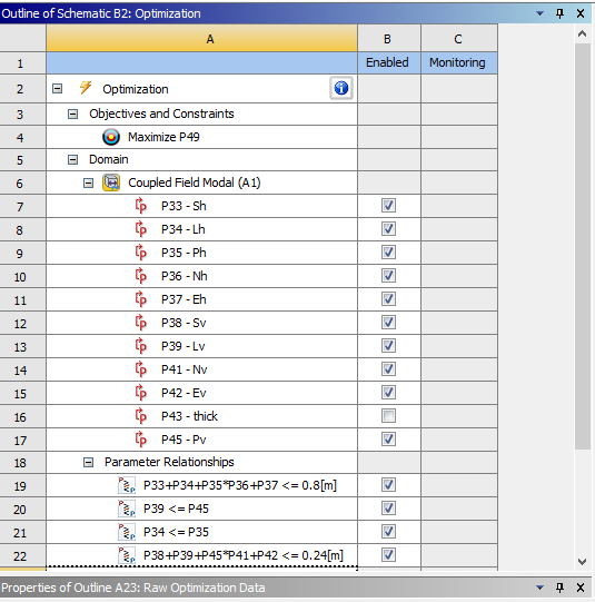
The next picture shows the constraints where l = Lh and Lv (for horizontal and vertical directions) and lp = Ph and Pv (for horizontal and vertical pitches).
I have tried to use such constraints before, which lead to an uneven / unsymetrical distribution for the generated design points of the optimization, as shown in the next picture.
-
January 3, 2024 at 5:52 pm
peteroznewman
SubscriberYou want the dimensions of the plate to be fixed at 0.8 x 0.24 and you want the pattern of patches to be placed at the center of the rectangle, making the margins to the edges of the plate to be equal. Is that right?
If so, you can't specify the dimension of the margin (S) as an input parameter. You must create an equation to calculate the margins from the patch parameters: L, N, P and the plate dimension.
-
January 3, 2024 at 9:44 pm
Md_Salem
SubscriberYou mean to set Sh (for example) as a target instead of H1 in the design modeler,then in the optimizer, exclude H1 from the parametrization process. And in this case, whatever the values of the other parameters, H1 will remain constant at 0.8 m.
I think this sounds good. I will try it.
Regards
-
January 4, 2024 at 2:41 am
peteroznewman
SubscriberYes, H1 = 0.8 m is a constant internal to DesignModeler. It is not a parameter and will not be seen by the Optimizer.
There is a new constraint: (Nh-1)*Ph + Lh <= 0.8 to prevent the array from exceeding the length of the plate. You also need the first constraint I mentioned before: Lh <= Ph
Write the equation for the horizontal length as 0.8 = (Nh-1)*Ph + Lh + 2*Sh but rearrange the equation to solve for Sh.
Sh = 0.8/2 – (Nh-1)*Ph/2 – Lh/2
The above equation is used in DesignModeler to dimension the horizontal offset to the start of the array. This equation guarantees that the array will be centered in the plate length of 0.8 m.
Add similar constraints for the vertical.
There is a new constraint: (Nv-1)*Pv + Lv <= 0.24 to prevent the array from exceeding the width of the plate. Still need the first constraint I mentioned before: Lv <= Pv
Write the equation for the vertical width as 0.24 = (Nv-1)*Pv + Lv + 2*Sv but rearrange the equation to solve for Sv.
Sv = 0.24/2 – (Nv-1)*Pv/2 – Lv/2
The above equation is used in DesignModeler to dimension the vertical offset to the start of the array. This equation guarantees that the array will be centered in the plate width of 0.24 m.
-
January 4, 2024 at 3:55 pm
Md_Salem
SubscriberHI,
I did it and tried to check some randomly generated design points. The generated geometrical configuration was totally perfect, as shown in the next picture.
I used the configuration you advised me to use next.
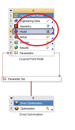
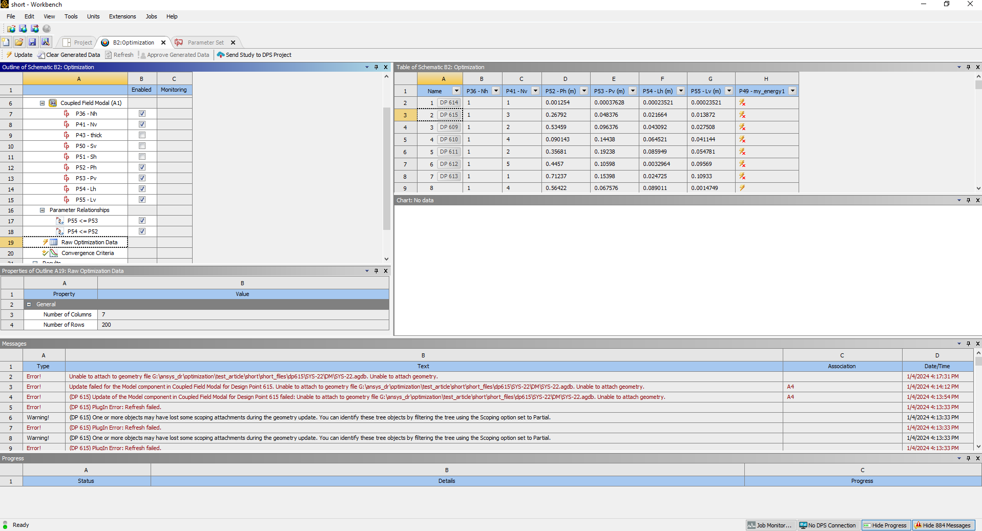
The problem this time was that the ANSYS workbench failed to import the generated geometry, as shown in the next pictures.
Despite using the right optimization configuration, as shown next
Regards
-
-
January 4, 2024 at 11:55 pm
peteroznewman
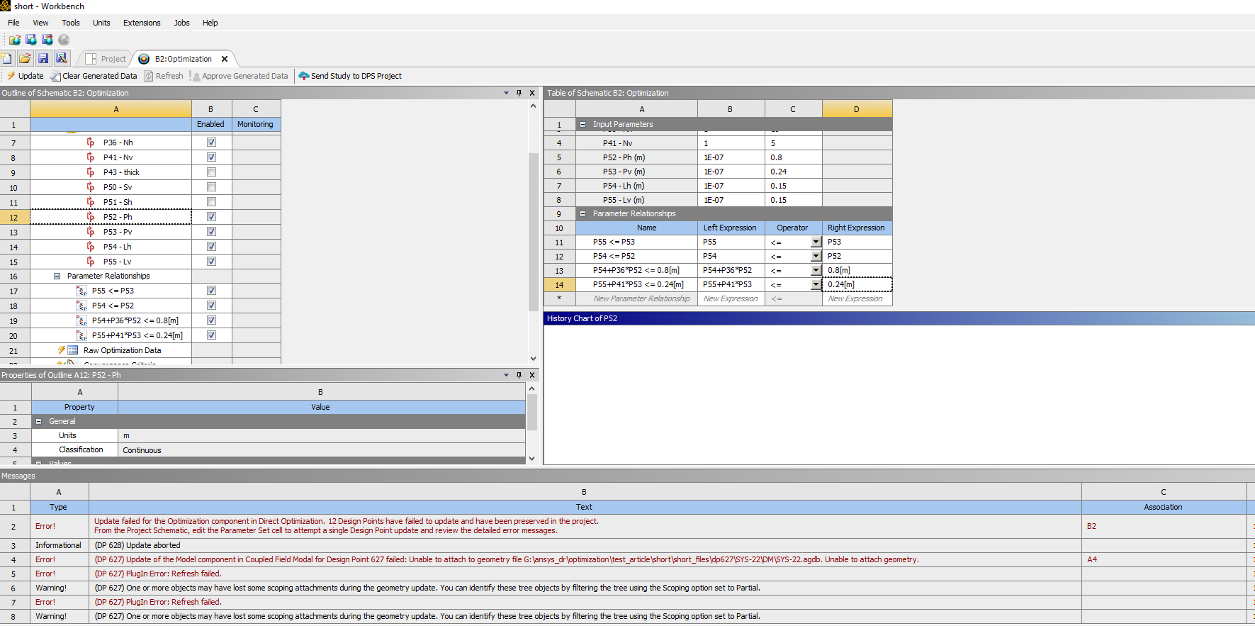
SubscriberI don't see the two new constraints I said to add to the two existing constraint I see above.
new constraint: (Nh-1)*Ph + Lh <= 0.8
new constraint: (Nv-1)*Pv + Lv <= 0.24
-
January 6, 2024 at 9:37 am
Md_Salem
SubscriberHello,
Kindly notice that it is supposed to be (Nh) and (Nv), not (Nh-1) or (Nv-1) since Nh and Nv denote the number of copies for the original patch in the horizontal and vertical directions, not the total number of patches in each direction.
Despite this, I added the constraint shown in the next picture.
Still, the problem of importing gemetrical configuration to the modal analysis
Regards
-
January 6, 2024 at 1:16 pm
peteroznewman
SubscriberThank you for correcting my mistake in the constraint equation. I noticed that you also corrected the DM equation for Sv and Sh.
The error message says that the Parameter set for each of the 12 failed Design Points have been preserved in the Project. The Parameter Set cell shows the input parameter values for each failed DP. The error message says to attempt a single DP update and review the detailed error messages. Have you done that?
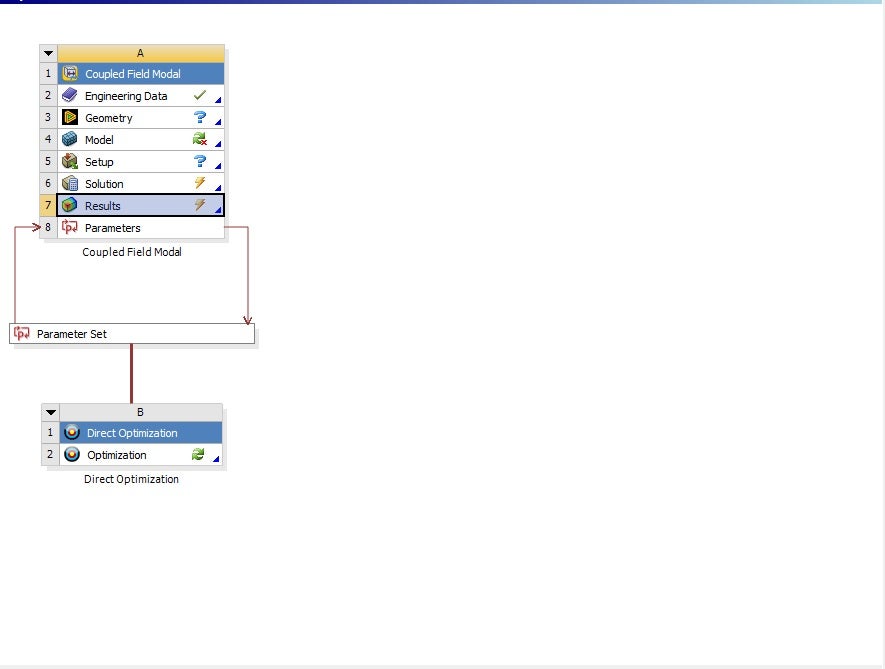
You could copy the input parameter values and manually input them into DM to check that they create valid geometry, then bring that geometry into a Coupled Field Modal analysis and verify that the geometry transfers in correctly and the model will solve.
-
January 23, 2024 at 10:26 pm
Md_Salem
SubscriberHello,
I tried to run the design points manually (one by one) to figure out where the fault is.
I discovered that there are two errors:
1st error:
when the number of replicants (Nh and Nv) is set to 1
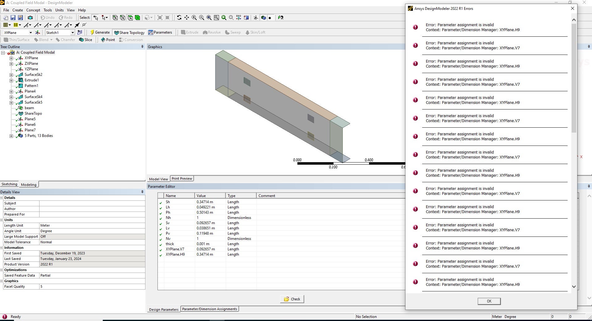
When I run the design point update, it gives me the next error.
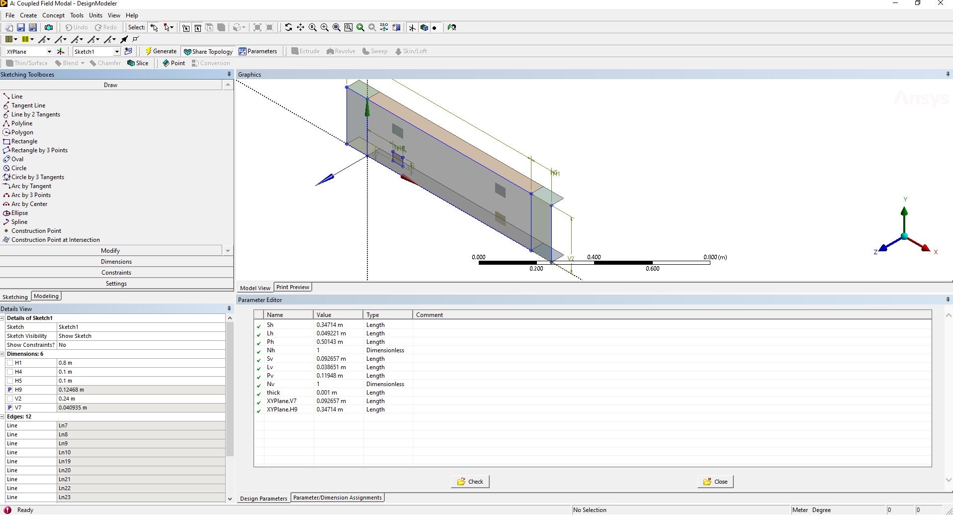
when I open the geometry cell I notice this red mark at the top left corner
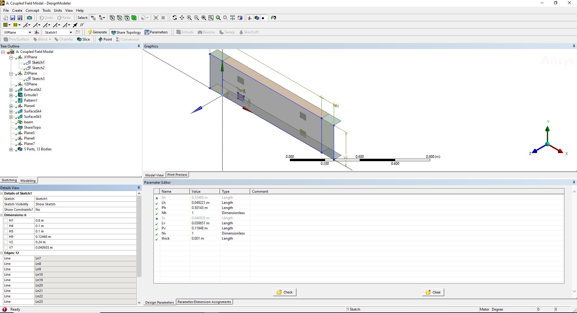
right click on that mark I recieve the shown error which inform me that there is problem about the parameters V7 and H9 which are set to be targets as (Sv, Sh) as shown in the previous disscusion
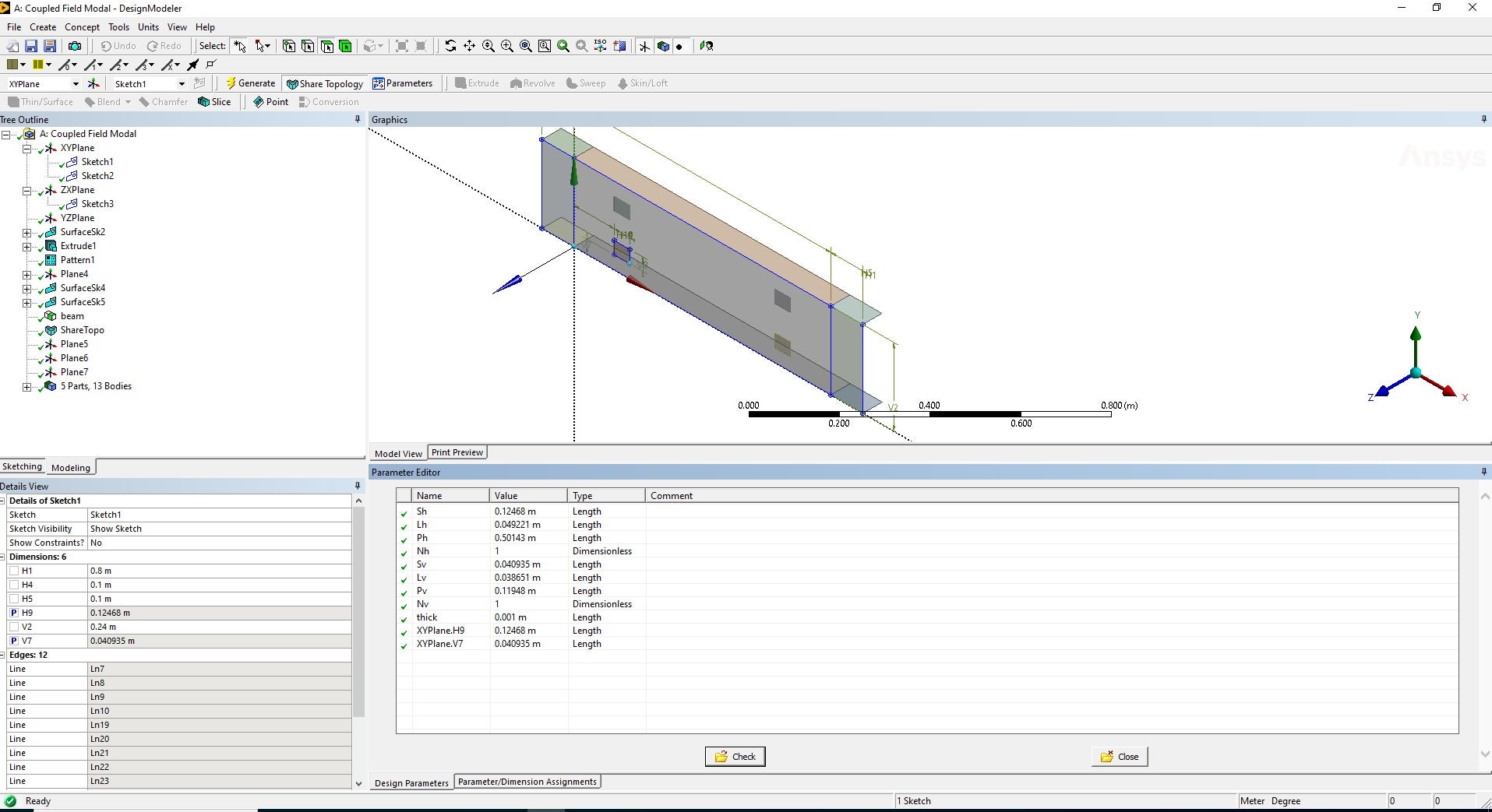
this situation is solved by unchecking the parametrizing box beside each of the two parameters and the re-check them again then click check button in the midle bottom
then the error desapear
and the rest of analysis is done properly
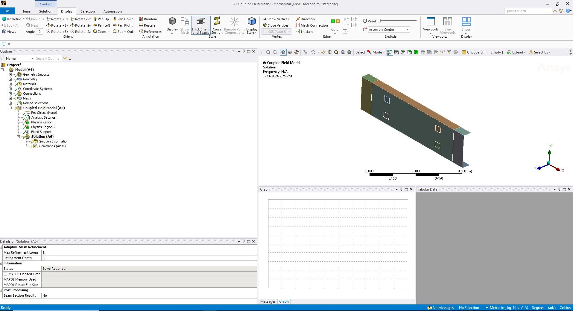
The second problem happens when Nh or Nv are larger than 1.
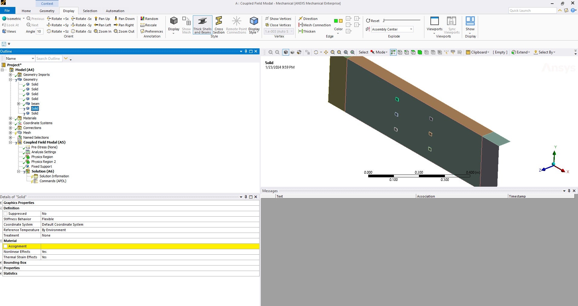
As shown in the next picture, even if I handled the parameter problem, another problem arose because the program failed to identify the material of the newly generated solid bodies!
would you help me to override these two problems?
Regards
-
January 24, 2024 at 12:16 am
-
January 25, 2024 at 12:02 pm
Md_Salem
Subscriber -
January 29, 2024 at 11:02 pm
Md_Salem
SubscriberHello,
I solved the 1st problem. The main cause of it was that I duplicated the identification of (H9 and V7) once as (@Sh,@Sv) and the other as targets for the two equality relationships, and this may have led to confusion of the solver. So, when I deteleted 1st identification (@Sh,@Sv) and just kept the 2nd identification as targets for the two equality relationships, it worked properly.
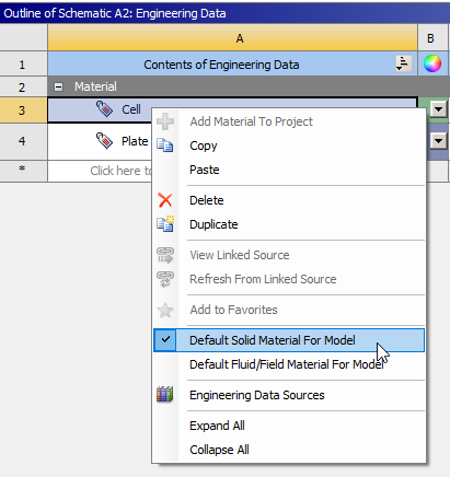
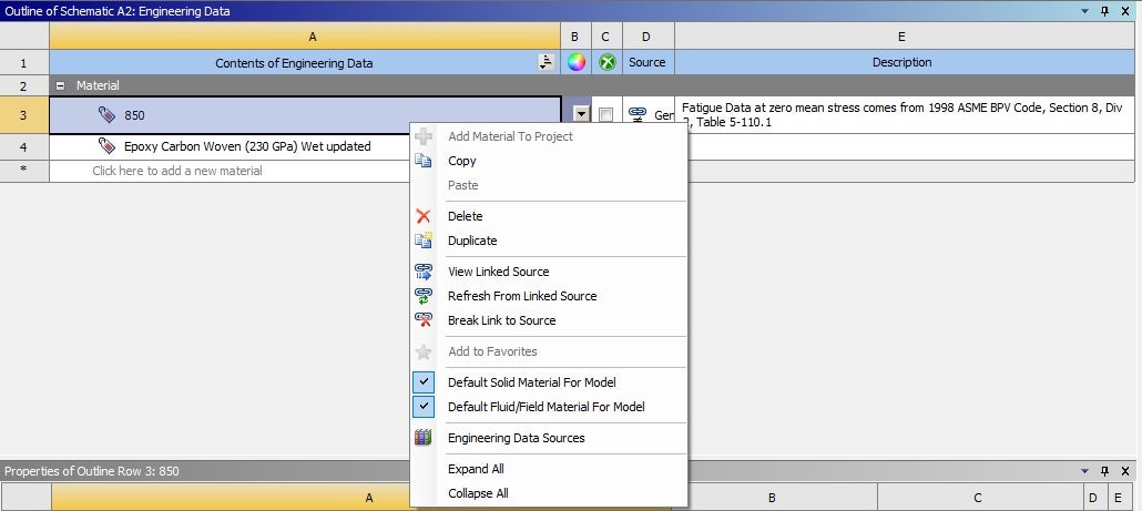
Unfortunately, I couldn't solve the second problem, despite doing as you told me, as shown in the next picture.
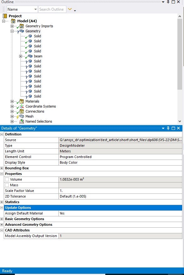
Further, I made sure that the default material update is "yes," as shown in the next picture.
What would you think is a probable cause for such a problem?
regards
-
- The topic ‘equality constraint in optimization’ is closed to new replies.


-
4673
-
1565
-
1386
-
1236
-
1021

© 2025 Copyright ANSYS, Inc. All rights reserved.

