-
-
November 15, 2023 at 10:33 pm
Issam EL KHADIRI
SubscriberHello
During the simulation the error appears to me
For pressure–velocity coupling, a segregated solver was used with the SIMPLE algorithm. The second-order upwind scheme was used to discretize the convective terms in the governing equations.
The residuals were set to 10−4 for continuity, 10−5 for momentum, and 10−6 for energy equations.
The number of iterations per time step was set to 20.
The time step size 0.001
number of time steps 5000
mesh: 500 000 element
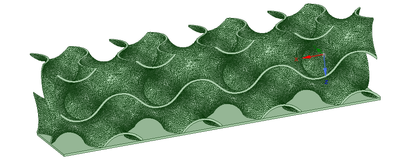
This is the geometry (heat sink TPMS) (Fluid: air, Solid: aluminum)
-
November 16, 2023 at 3:45 pm
Rob
Forum ModeratorWhat's the mesh quality like?
-
November 16, 2023 at 10:25 pm
Issam EL KHADIRI
SubscriberHellom
Thank you for your answer,
This is the Report quality:
Mesh Quality:
Minimum Orthogonal Quality = 3.24228e-07 cell 86742 on zone 6 (ID: 1279410 on partition: 2) at location ( 1.00402e-02 7.34195e-03 3.86050e-03)
(To improve Orthogonal quality , use "Inverse Orthogonal Quality" in Fluent Meshing,
where Inverse Orthogonal Quality = 1 - Orthogonal Quality)
Warning: minimum Orthogonal Quality below 0.01.Maximum Aspect Ratio = 1.34494e+03 cell 296109 on zone 6 (ID: 1115234 on partition: 2) at location ( 5.03466e-02 1.06909e-03 -8.35610e-03)
Fluent can try to improve the mesh quality via the TUI command
/mesh/repair-improve/improve-quality
Domain Extents:
x-coordinate: min (m) = -9.000000e-02, max (m) = 1.500000e-01
y-coordinate: min (m) = -1.000664e-02, max (m) = 1.000000e-02
z-coordinate: min (m) = -1.000000e-02, max (m) = 1.050000e-02
Volume statistics:
minimum volume (m3): 8.992539e-16
maximum volume (m3): 6.769667e-10
total volume (m3): 9.907077e-05
Face area statistics:
minimum face area (m2): 7.985135e-11
maximum face area (m2): 1.673634e-06
Checking mesh.....................................
Done. -
November 17, 2023 at 1:13 am
Issam EL KHADIRI
SubscriberI reduced the mesh to 10 million elements, but the problem persists until now
-
November 17, 2023 at 9:16 am
Rob
Forum ModeratorYes, it's the mesh. Min ortho quality of 0.05 is considered to be poor quality, you're somewhat below that. Similarly aspect ratio has some leeway for inflation, but 1,300 is very high.
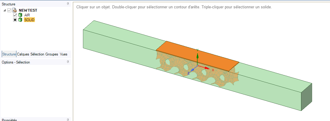
Looking at the second image, check the walls bounding the flow that cut the structure don't have narrow gaps or crevices which then cause the skew cells.
-
November 17, 2023 at 4:11 pm
Issam EL KHADIRI
SubscriberI reduced the meshing from half a million to 10 million elements to reduce the effect of meshing
I also checked that the geometry does not have any gaps or crevices.
But no change, the problem still existsCould the problem be somewhere other than the mesh or the geometry?
-
November 20, 2023 at 10:48 am
Rob
Forum ModeratorAnd what did that do to the cell quality?
-
November 23, 2023 at 12:02 am
Issam EL KHADIRI
SubscriberThe problem has been solved. You were right. There was a problem with the mesh.
thank you for your help -
November 23, 2023 at 12:12 am
Issam EL KHADIRI
Subscriber -
November 23, 2023 at 11:17 am
Rob
Forum ModeratorThat means you've managed to mesh both zones but not split the solid from the fluid: that may explain the improvement in cell quality.
-
November 23, 2023 at 11:41 am
-
November 23, 2023 at 11:44 am
Rob
Forum ModeratorTry subtract. Unless you really want to see the solid heat up you don't need it in the CFD model.
-
November 23, 2023 at 11:47 am
Issam EL KHADIRI
SubscriberI need to see the heating of the solid with the velocity of the fluid and show the turbulence
-
November 23, 2023 at 11:49 am
Rob
Forum ModeratorOK, so you'll need to subtract and retain the solid and then share topology. The terms etc are covered in the tutorials, and I advise having a look at the various conjugate heat transfer tutorials/videos on the Ansys system.
-
November 23, 2023 at 12:02 pm
Issam EL KHADIRI
SubscriberI think that the solid is separated from the fluid because I named each of them in the meshing stage along with naming the boundary conditions/regions. with contact surface
-
November 23, 2023 at 1:16 pm
Rob
Forum ModeratorYou've got wall and wall shadow in Fluent and assigned the solid material to the metal part? If you have done that how are the pathlines going through the metal part?
-
- The topic ‘Energy Equation Divergence ansys divergence’ is closed to new replies.


-
4838
-
1587
-
1386
-
1242
-
1021

© 2026 Copyright ANSYS, Inc. All rights reserved.


