-
-
May 12, 2024 at 3:06 am
profiterol 1
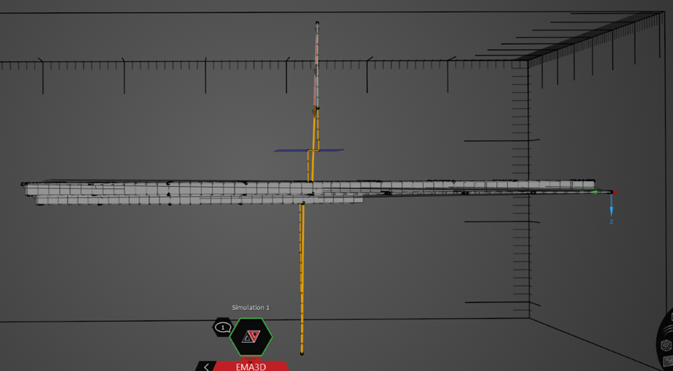
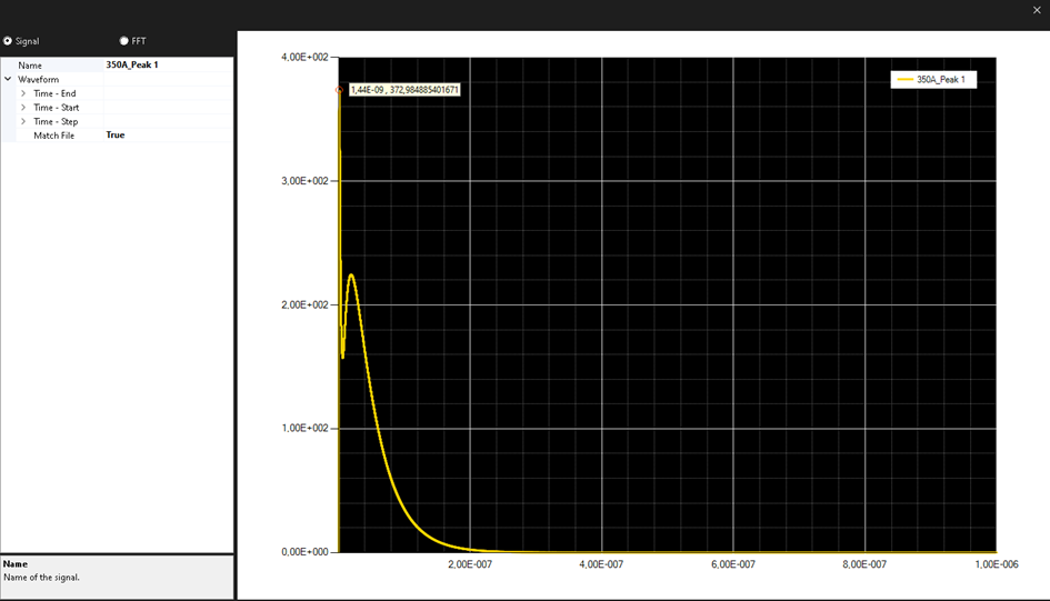
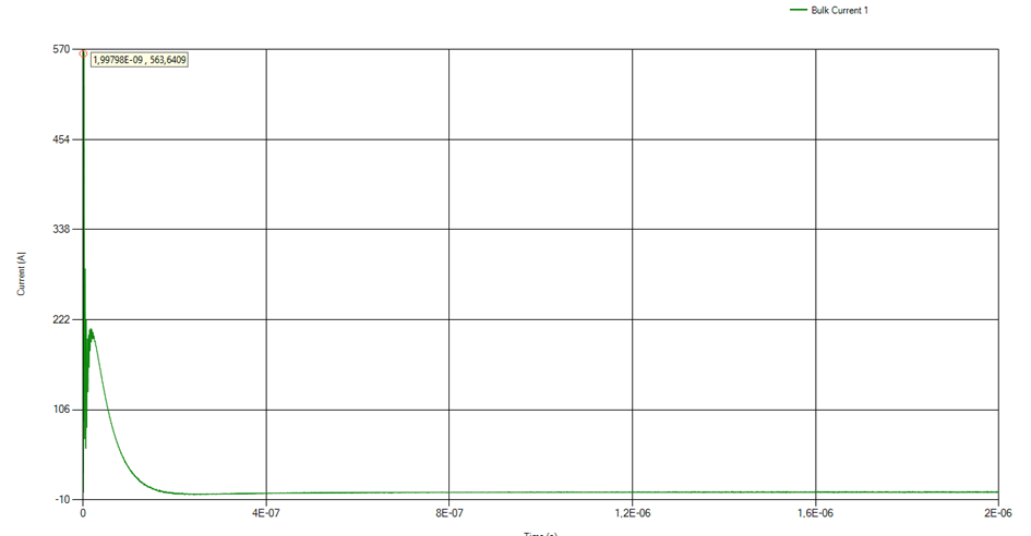
SubscriberHello, I want to do an ESD simulation. I used a current source, and the peak value of the signal I used in this source is around 375A. I'm using a current probe to monitor the current flowing from the current source, and when I take measurements from the probe, the peak level of the current is around 575A, which is an undesired situation. (I assigned the current source to the line first, then divided the line into two and assigned the part in contact with the object as PEC. In other words, there is a connection from the domain to the current source, and the current source is connected to the PEC, and the PEC is in contact with the object. I'm taking measurements via PEC.)

I also connected the object to the lower domain with PEC. The meshes can be seen in the attached image. The mesh of the source looks strange; I originally used a straight line, but in the mesh view, it appears as angular lines. Could this be causing the issue? I believe that to conduct a proper simulation, I should see the same current applied to the source reflected in the current probe. Can you help me with this?
Applied waveform
Measured Signal
-
October 2, 2024 at 11:29 am
Aymen Mzoughi
Ansys EmployeeIt's hard to give an answer without investigating the project
-
- The topic ‘EMA3D Current Source Problem’ is closed to new replies.


- Three-Phase Voltage Imbalances in dual stator electric generator
- Link the Circuit to 3D Terminals
- Magnetic Dipole moment calculation
- Integration lines or U Axis Line for circular and rectangular ports
- Core Loss in ANSYS MAXWELL Eddy Current solution
- exporting and importing my Netlist for my external circuit
- Error of Metal Fraction in Icepak Classic.
- The unit of theta in Is*sin(2*pi*fre*Time+theta-2*pi/3)
- 2D transient simulation -torque issue
- Two way coupling for Maxwell and thermal problem

-
4618
-
1530
-
1386
-
1209
-
1021

© 2025 Copyright ANSYS, Inc. All rights reserved.


