TAGGED: error-001100247
-
-
September 25, 2022 at 11:22 am
up1057819
SubscriberHello everyone,ÂÂI am running a large deflection analysis with mechanical Apdl ( NLGEOM, ON). As soon as the loading initiates the solution collapses and I get an error message that a particular element has exceeded distortion. When I check the elements ( SHELL181 Quad node element)Â deformation it changes from a rectangular shape to a completely irregular one.ÂÂ I have tried to reduce the time step and increase the number of substeps but nothing worked.Why this error occurs?ÂÂ -
September 25, 2022 at 12:03 pm
peteroznewman
SubscriberDoes it solve with NLGEOM turned off?
You might have a mistake in the model. Check the magnitude of the loads and check the values of the material properties. Check the thickness property of the shell element. Reduce the load by a factor of 10^3 and try that. Reduce the load by a factor of 10^6 and try that.
-
September 25, 2022 at 2:30 pm
up1057819
SubscriberYes, it solves when the NLGEOM is off. I tried that but didn't work.If the problem is related to the connection of the elements how could I solve for that?Â
Â
-
September 25, 2022 at 6:38 pm
peteroznewman
SubscriberIf it solves as a linear solution, it is unlikely to be an issue with element connectivity.
Please reply with images of the mesh, load and boundary conditions.
-
September 25, 2022 at 10:12 pm
up1057819
SubscriberHere is an image of the model. The seen are restrained in ux,uy, and the first node of the row in ux,uy,uz (only one node is restrained in all three degrees of freedom). The whole structure is meshed witth an element size 0.5 ( esize=0.5). The load is applied in a form of a displacement( seen in the second picture) firstly the nodes are given a displacement equal to 10mm in the uy direction(vertical) and then in the -ux equal to 0.5. this is done in order to simulate shear stress in the core.The model is connected with AOVLAP command. Hope this is enough for you.
Â
Â
-
September 26, 2022 at 2:34 am
peteroznewman
SubscriberWhat is the goal or purpose of this analysis? What is it that you want the results to tell you? Are you looking to calculate the shear modulus of the core in a specific direction?
In the graphics, I can see a row of ux, uy constraints on one edge of the top facesheet and I understand the corner node is constrained in x,y, and z. Having one straight line of nodes like that creates a hinge.Â
In the second image, it's not clear which nodes are given a displacement. I also don't know how thick is the core compared with the 10 mm displacement you mentioned.
I recommend switching to applied forces and don't use any applied displacements.
Â
-
September 26, 2022 at 8:19 am
up1057819
SubscriberThe purpose of the analysis is to examine some shear stresses. The 10 mm is the same as the thick of the core. I cannot use force because I don't know the magnitudeÂ
-
September 26, 2022 at 3:22 pm
peteroznewman
SubscriberA 10 mm thick displacement of the bottom facesheet relative to the top facesheet with a 10 mm thick core is an absurdly large amount. What is core material and wall thickness? What is the facesheet material and thickness?
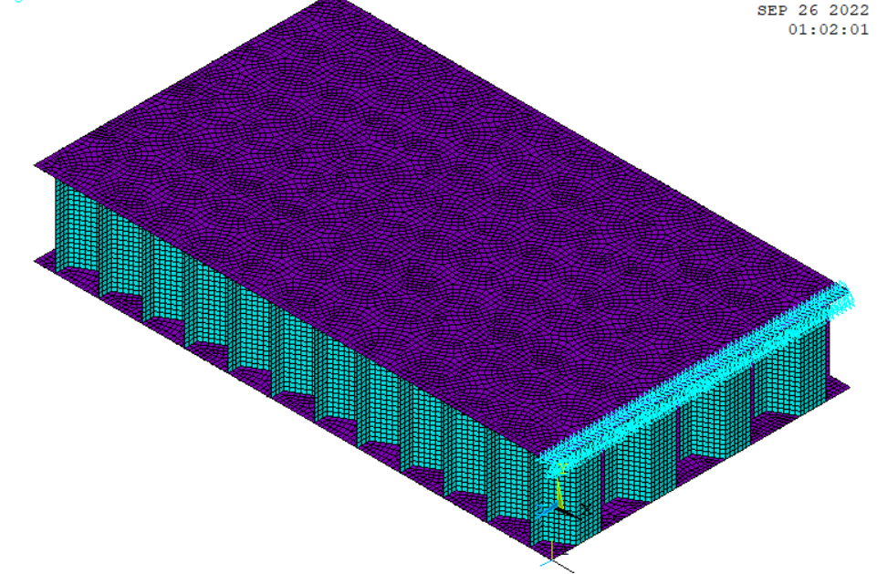
Is the core manufactured by corrigating and bonding two thin sheets together? That creates a double thick wall in one direction. Did you do that in your model?
Here is the test apparatus from ASTM C273 -11 Standard Test Method for Shear Properties of Sandwich Core Material.
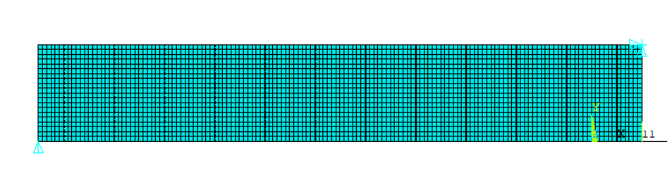
If you don't want to switch to Force, I recommend that you select the row of nodes on the bottom facesheet at the opposite end of the sandwich from the row that has the x,y constraints on the top face sheet. Use a Displacement of Y=0 to prevent rotation about the first edge. Is the sample 50 mm long? In that case, 1% strain would be 0.5 mm. Use a Displacement of X= -0.5 mm to those bottom edge nodes to put the facesheets into tension at each end. Use 100 initial and minimum substeps, 1000 substeps maximum, in the solution.
-
- The topic ‘Element has excessive distortion.’ is closed to new replies.
- acces to path ‘session_files’ is denied error
- Fluent and Rocky DEM coupling in Ansys student
- ANSYS 2024 R2 Student License Manager Error
- unexpected license problem; exiting. hit return to exit.
- Ansys Student 2025 R1 – Ansys Discovery did not install
- No FlexNet Publisher (FNP) license found for feature HPC Parallel.
- Ansys Electronics Desktop crashes when trying to set the steel type in RMXprt
- Can not find Spaceclaim option in ANSYS2024R2 workbench
- Workbench application not showing up after installing Ansys Student 2024 R2
-
2262
-
925
-
599
-
591
-
497
© 2025 Copyright ANSYS, Inc. All rights reserved.