-
-
March 11, 2024 at 5:43 pm
George Nelson
SubscriberHello, I am trying to simulate SiN waveguide to SMF and extract the S parameters or just see the transmission into the fiber mode to get the coupling loss.
I do not use ports because I break up the simulation into two parts and ports cannot export/import sources. I followed this example to perform the export/import: https://optics.ansys.com/hc/en-us/articles/360034383034-Using-monitor-data-to-define-the-spatial-field-profile-of-a-source-in-FDTD
Part 1) The inverse taper in the SiN waveguide to convert/expand the mode to better match MFD of the fiber. I use a mode source going towards the fiber from the nominal WG width and I export the fields just before the interface to the fiber.
Part 2) The WG to SMF interface. On the PIC side, I import the source using the export from part 1. On the fiber side, I have modal expansion and DFT monitors tied together to get the transmission into the fiber mode.
My original modal source for part 1 is the fundamental TE mode (it's TE mode WG), I set wavelength from 1.5um to 1.6um, my mesh setting is "3" and I
When I try to change the inverse taper to help me design the coupler and find the correct length, sometimes I get reasonably results, but mostly I don't. See these videos:
300um taper 1500nm to 250nm:
200um taper 1500nm to 250nm:
100um taper 1500nm to 250nm:
The 300um one works as I expect and I get reasonable result at the end (total transmission into fiber mode ~50% or -3dB). However the 200um and 100um I get a very long simulation where a strange field grows from the PIC side. You can easily see in the videos at the end. This field can't be physical and I must have something set incorrectly, any ideas?
Also, you can see all the videos the majority of the time nothing is happening. Is there any way to speed this up and simulate only the important parts?
Thank you,
George
-
March 12, 2024 at 4:46 pm
Guilin Sun
Ansys EmployeeIt seems PML reflection plays role here, as the main pulse signal has already passed the interface.
Since you only want to get the coupling efficiency between the fiber and the taper end, you only need to simulate short distance around the interface. No need to include long fiber and long taper. Please check the taper mode fiels near its end and see if higher order modes are excited. Even if they are excited, you can import them as a whole to be the excitation source. By this way the simulation volume is greatly reduced so you can use much thicker PML, eg more PML layers. There is no resonance at such interface, so short simulation time should be fine.
It is obvious that the right side PML has issues. and seems the fields have "difficulty" to propagate. The simulation will diverge evetually.
When the source is imported with broadband data, it needs time to prepare the actual signal. It also takes time for signal starting from zero to its peak value. You have offset time period at the source, which should be since the signal should not start abruptly.
The imported broadband source will take much longer time if you choose too many frequency points. Usually 20 to 30 should be enough.
Make sure you really need such broadband source.
-
March 20, 2024 at 9:51 pm
George Nelson
SubscriberThanks to your pointing out that it is related to PML, I managed to fix the obvious problem in the videos. Here is the 100um taper result with the Xmax boundary set to stabilized PML setting:
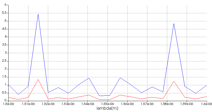
However, I noticed it still takes reaches the time limit set for the simulation instead of the early shutoff. The early shutoff does get triggered for 300um taper. I get >100% total transmission in for some wavelengths, too, so the mesh density or simulation accuracy must not be good enough. The simulations are already taking too long, so rather than increasing mesh density I will try to approach this problem some other way that is faster. I think I will start on the Fiber side rather than on the taper side first.
Final Results:
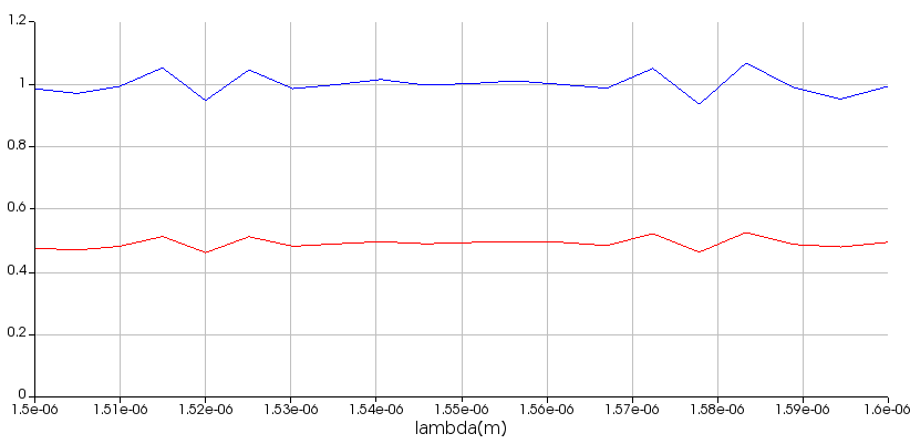
300um taper (Blue is total transmission, Red is transmission into fiber mode), looks ok:
100um taper, looks like accuracy is poor:
-
March 20, 2024 at 10:07 pm
Guilin Sun
Ansys EmployeeThe larger-than-1 result may indicate that the simulation time is not long enough. What is the persentage from log file at the end of simulation?
To make the simulation stable, I personally do not use stabilized PML, as it can have large reflections. You should use standard PML with 64 layers. If this is not suffiicent, you can use the "custom PML", with the PML parametes the same as the Standard, and just increase the max PML layers and use it, say to 128 or more.
Since the device is long, the long simulation time is expected. You can simulate short staright waveguide/fiber with long taper part, use long enough simulation time say 10 times or more than you used right now, and let the autoshutoff min to terminate the simulation .
In addition, you can also use a time monitor at the far end and check its spectrum to see if there is srong resonance, which should not in such device.
You can also use more frequency points in the transmission monitor to have smoother result.
-
March 20, 2024 at 10:54 pm
George Nelson
SubscriberSimulation time is currently 10,000 fs. The simulation progress was 99.3% on the last log line before the end. My min shutoff is 1e-5.
I have a check point saved right before the end. Can I change the simulation time and load the checkpoint? Or do I have to re-run the entire simulation?
What about DFT and mode monitor frequency points, can those be changed somehow without re-running the simulation? I'm assuming no but just checking. The simulation takes a few days on my computer.
-
March 20, 2024 at 11:49 pm
Guilin Sun
Ansys EmployeePlease refer to overcome the diverging issue:
Troubleshooting diverging simulations in FDTD
No you cannot change the simulation time bu checkpoint. It can only change the autoshutoff value. This is why I suggest you to use much longer simulation time.
No you cannot change the monitor settings without redoing the simulation.
I am not sure how much memory it needs. Usually the simulation time should be much less than what you said, for device ~300um. You may need to upgrade your computer to have better performance: Information on Hardware Specifications
The computer and the software are the tools for you to do your projects. if the tools are not proper, your progress on the projects may be hindered.
-
- The topic ‘Edge Coupler SiN waveguide to SMF fiber Strange Field Problem’ is closed to new replies.


-
4904
-
1598
-
1386
-
1242
-
1021

© 2026 Copyright ANSYS, Inc. All rights reserved.


